
Surface lighting module and surface lighting source device for a vehicle using the same

a technology of surface lighting and source device, which is applied in the direction of lighting and heating apparatus, semiconductor devices for light sources, instruments, etc., can solve the problems of increasing components cost, deteriorating light efficiency of components, and increasing components cost, so as to improve marketability, improve surface lighting efficiency, and reduce costs

Inactive Publication Date: 2017-12-28
HYUNDAI MOTOR CO LTD
View PDF6 Cites 3 Cited by
  • Summary
  • Abstract
  • Description
  • Claims
  • Application Information

AI Technical Summary

Benefits of technology

The present invention provides a surface lighting module and a surface lighting source device for a vehicle that can improve efficiency, reduce costs, and increase marketability. By adding a reflector that can reflect light leaking to a lateral surface of a light guide member, the number of LEDs needed can be minimized, fuel efficiency can be improved, and the size, thickness, and weight of components of the vehicle can be reduced. Additionally, preventing light from leaking and improving light extraction efficiency, as well as improving durability and light color quality, can be achieved by reducing the number of LEDs.

Problems solved by technology

In the aforementioned technologies, important issues are associated with allowing the surface that emits light to have uniform brightness, and the backlighting technology as a technology for emitting light of the most uniform brightness allows the light of the LED to be emitted from a lateral surface of a light guide element.
However, since two or more LEDs 1 and 2 are used to cover a symbol area of the BSD with uniform lighting and to secure required brightness, costs of components thereof increase.
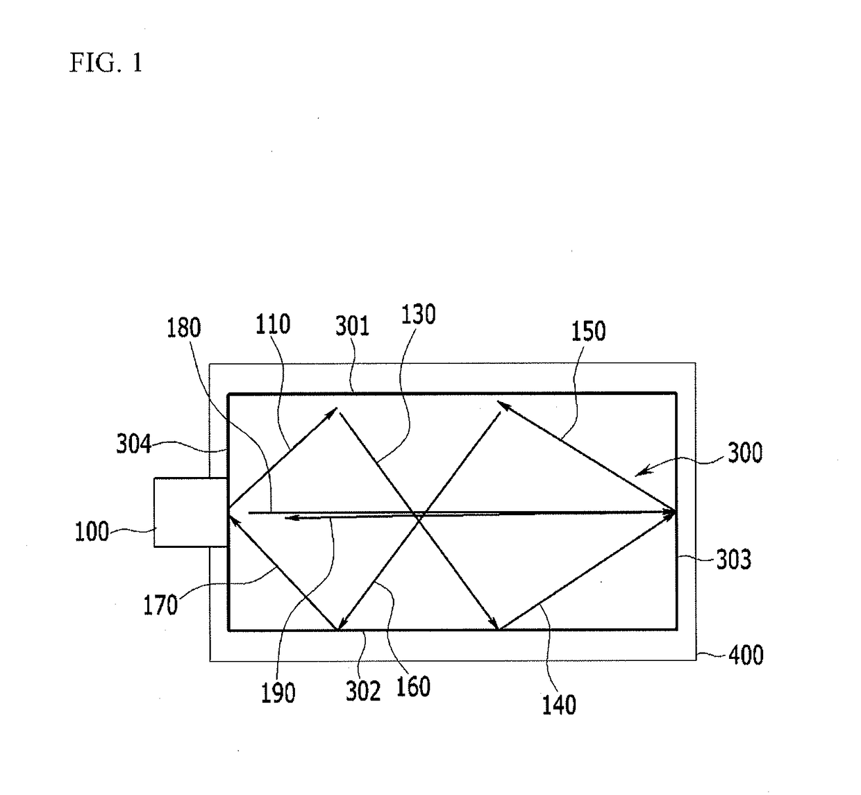
However, in the conventional BSD, since the light is not reflected by a lateral surface of the light guide element, light efficiency thereof deteriorates, and many LEDs should be used due to the deterioration of light efficiency, thereby increasing costs of components.

Method used


Image

  • Surface lighting module and surface lighting source device for a vehicle using the same
  • Surface lighting module and surface lighting source device for a vehicle using the same
  • Surface lighting module and surface lighting source device for a vehicle using the same

Examples


Embodiment Construction

[0048]Reference will now be made in detail to various embodiments of the present invention(s), examples of which are illustrated in the accompanying drawings and described below. While the invention(s) will be described in conjunction with exemplary embodiments, it will be understood that the present description is not intended to limit the invention(s) to those exemplary embodiments. On the contrary, the invention(s) is / are intended to cover not only the exemplary embodiments, but also various alternatives, modifications, equivalents and other embodiments, which may be included within the spirit and scope of the invention as defined by the appended claims.

[0049]An exemplary embodiment of the present invention will hereinafter be described in detail with reference to the accompanying drawings.

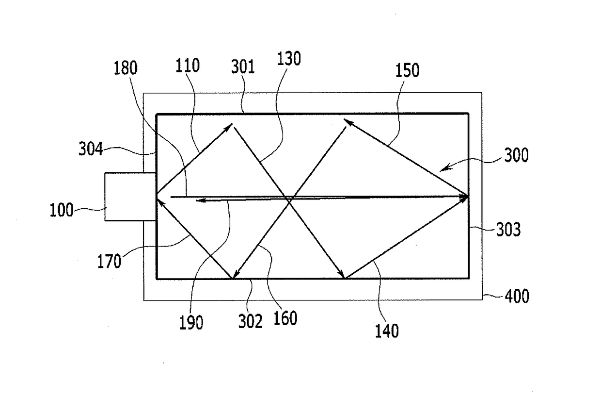
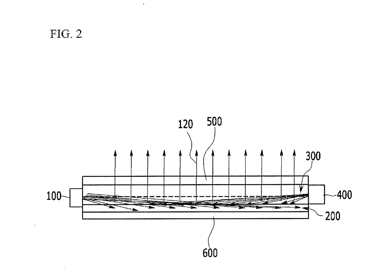
[0050]FIG. 1 illustrates a top plan view of a surface lighting module according to an exemplary embodiment of the present invention, FIG. 2 illustrates a side cross-sectional view of a surface ...


PUM


Abstract

A surface lighting module may include: a light source configured to emit light; a main reflection part configured to reflect light emitted from the light source; a light guiding part that is provided at an upper portion of the main reflection part and spreads light reflected from the main reflection part to have a surface shape; and a lateral reflection part that is attached to a lateral surface of the light guiding part and reflects light leaking to the lateral surface of the light guiding part.

Description

CROSS-REFERENCE TO RELATED APPLICATION[0001]The present application claims priority to and the benefit of Korean Patent Application No. 10-2016-0081056 filed on Jun. 28, 2016, the entire contents of which are incorporated herein by reference.BACKGROUND OF THE INVENTIONField of the Invention[0002]The present invention relates to a surface lighting module and a surface lighting source device for a vehicle using the same. More particularly, the present invention relates to a surface lighting module and a surface lighting source device for a vehicle using the same that may enhance marketability thereof and may reduce costs thereof by improving efficiency of surface lighting which may be generated by lighting devices for the vehicle used for various purposes.Description of Related Art[0003]In general, for various purposes and for providing luxury senses to a user, a lighting module is applied to various components of a vehicle.[0004]For example, a surface lighting modules forming surface...

Claims


Application Information

Patent Timeline
Patent Type & Authority Applications(United States)
IPC IPC(8): B60Q3/10F21V8/00B60Q3/20
CPCG02B6/0055G02B6/0063B60Q3/10G02B6/0065B60Q3/20G02B6/0073F21K9/61F21V7/24F21V7/0066F21Y2105/18F21Y2105/16F21Y2115/10F21W2107/00Y10S362/80
Inventor KANG, CHAN HEE
Owner HYUNDAI MOTOR CO LTD
Learn More