
Welding scheme for crown wear-resistant block of single crystal turbine blade

A technology for turbine blades and wear-resistant blocks, which is applied in welding equipment, arc welding equipment, manufacturing tools, etc., and can solve the problem of poor bonding between the substrate and wear-resistant blocks, poor wettability of wear-resistant blocks, and solder joints at the trailing edge Problems such as clogging can be avoided, achieving high pass rate, avoiding repeated brazing, and ensuring the effect of processing quality

Inactive Publication Date: 2018-06-12
GUIYANG AVIC POWER PRECISION CASTING
View PDF7 Cites 2 Cited by
  • Summary
  • Abstract
  • Description
  • Claims
  • Application Information

AI Technical Summary

Problems solved by technology

[0003] The design requires the use of vacuum brazing to weld the wear-resistant block on the blade crown. Since the thickness of the wear-resistant block is 1.4mm, it is too thick to be suitable for brazing. In addition, the wettability of the solder to the wear-resistant block is not good, resulting in The bonding force between the matrix and the wear-resistant block is poor. After brazing, the wear-resistant block is easy to fall off. Repeated brazing, coupled with the good fluidity of the brazing material, is likely to cause the tail edge split seam to be blocked by solder, resulting in scrapping of the blade. Serious Affected the normal delivery of blades

Method used


Image

  • Welding scheme for crown wear-resistant block of single crystal turbine blade
  • Welding scheme for crown wear-resistant block of single crystal turbine blade

Examples


Embodiment Construction

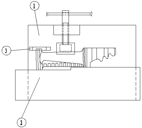
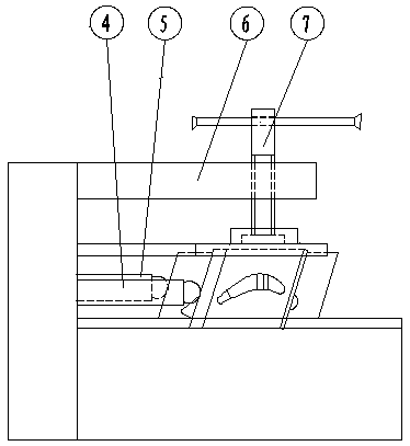
[0031] The specific implementation, structure, features and effects of a welding scheme for a wear-resistant block of a single crystal turbine blade shroud according to the present invention will be described in detail below in conjunction with the accompanying drawings and preferred embodiments.

[0032] See attached Figure 1-2 , the welding scheme of a single crystal turbine blade crown wear block provided by the present invention mainly includes the following steps:

[0033] 1) Prepare the turbine blade to be welded, and grind the blade crown surface to be welded to remove the oxide layer;

[0034] 2) Fix the turbine blade to be welded by a fixture, and ensure good contact of the conductive surface during welding;

[0035] 3) Turn on the argon arc welding machine and adjust the welding current to 35A;

[0036] 4) Adjust the amount of argon to 10 / min;

[0037] 5) Install the tungsten electrode on the nozzle of the welding torch;

[0038] 6) Move the welding wire and the...


PUM

PropertyMeasurementUnit
thicknessaaaaaaaaaa
thicknessaaaaaaaaaa

Abstract

The invention provides a welding scheme for a crown wear-resistant block of a single crystal turbine blade and relates to the technical field of non-traditional machining. According to the welding scheme, welding current is adjusted to be 30-45 A, the amount of argon is adjusted to be 8-12 L / min, and the crown part of the blade fixed on a fixture is subjected to surfacing for 1-5 s; then the surfacing effect is checked, whether an alloy is full, whether a corner R is provided with holes and whether a welding part has crack defects are checked, and blades with defective appearance are removed;hardness of substrates of an accumulation layer and a surfacing position, crystalline phase structure of the substrates in the surfacing position, welding quality and depth of a fusion layer at a weldjoint are subjected to metallographic inspection. The condition of falling of the wear-resistant block after welding can be solved, repeated brazing caused by falling of the wear-resistant block during brazing is avoided, so that production time is saved, cost is saved, qualification rate of argon arc welding surfacing is high, machining quality is guaranteed, and production efficiency is improved.

Description

technical field [0001] The invention relates to the technical field of special processing, in particular to a welding scheme of a wear-resistant block of a single crystal turbine blade crown. Background technique [0002] The working blade of a certain turbine is a complex air-cooled hollow single crystal blade. Its shape is composed of a blade body, a blade crown and a tenon. [0003] The design requires the use of vacuum brazing to weld the wear-resistant block on the blade crown. Since the thickness of the wear-resistant block is 1.4mm, it is too thick to be suitable for brazing. In addition, the wettability of the solder to the wear-resistant block is not good, resulting in The bonding force between the matrix and the wear-resistant block is poor. After brazing, the wear-resistant block is easy to fall off. Repeated brazing, coupled with the good fluidity of the brazing material, is likely to cause the tail edge split seam to be blocked by solder, resulting in scrapping ...

Claims


Application Information

Patent Timeline
Patent Type & Authority Applications(China)
IPC IPC(8): B23K9/167B23K9/235
CPCB23K9/167B23K9/235
Inventor 赵前松马启伟代祥勇余昌奎王林伟
Owner GUIYANG AVIC POWER PRECISION CASTING
Learn More