Cleaning apparatus, plating apparatus using the same, and cleaning method

a technology of cleaning apparatus and plating apparatus, which is applied in the direction of cleaning using liquids, electrolysis components, chemistry apparatus and processes, etc., can solve the problems of inability to clean and dry a large rectangular substrate, inability to clean and dry a large circular substrate, and difficulty in cleaning and drying the substrate through the srd

Active Publication Date: 2017-12-28
EBARA CORP
View PDF7 Cites 6 Cited by
  • Summary
  • Abstract
  • Description
  • Claims
  • Application Information

AI Technical Summary

Problems solved by technology

A typical SRD is configured to clean a substrate having a predetermined size, and thus potentially unable to clean and dry a large rectangular substrate.
When having a small stiffness, a rectangular substrate potentially becomes curved, which makes it difficult to clean and dry the substrate appropriately through the SRD.
Similarly, the SRD is unable to clean and dry a large circular substrate in some cases.
Thus, when the substrate is cleaned by the cleaning apparatuses disclosed in Japanese Patent Laid-Open No. 2010-64196 and Japanese Patent Laid-Open No. 2008-110471 while a sponge is directly in contact with the surface of the substrate, the resist pattern potentially flakes into particles and adheres to the rectangular substrate, or the wiring pattern potentially breaks.
Similarly, the cleaning apparatuses disclosed in Japanese Patent Laid-Open No. 2010-64196 and Japanese Patent Laid-Open No. 2008-110471 can cause the same problem on a circular substrate.

Method used


Image

  • Cleaning apparatus, plating apparatus using the same, and cleaning method
  • Cleaning apparatus, plating apparatus using the same, and cleaning method
  • Cleaning apparatus, plating apparatus using the same, and cleaning method

Examples


Embodiment Construction

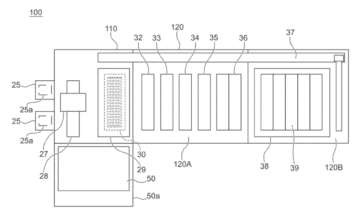
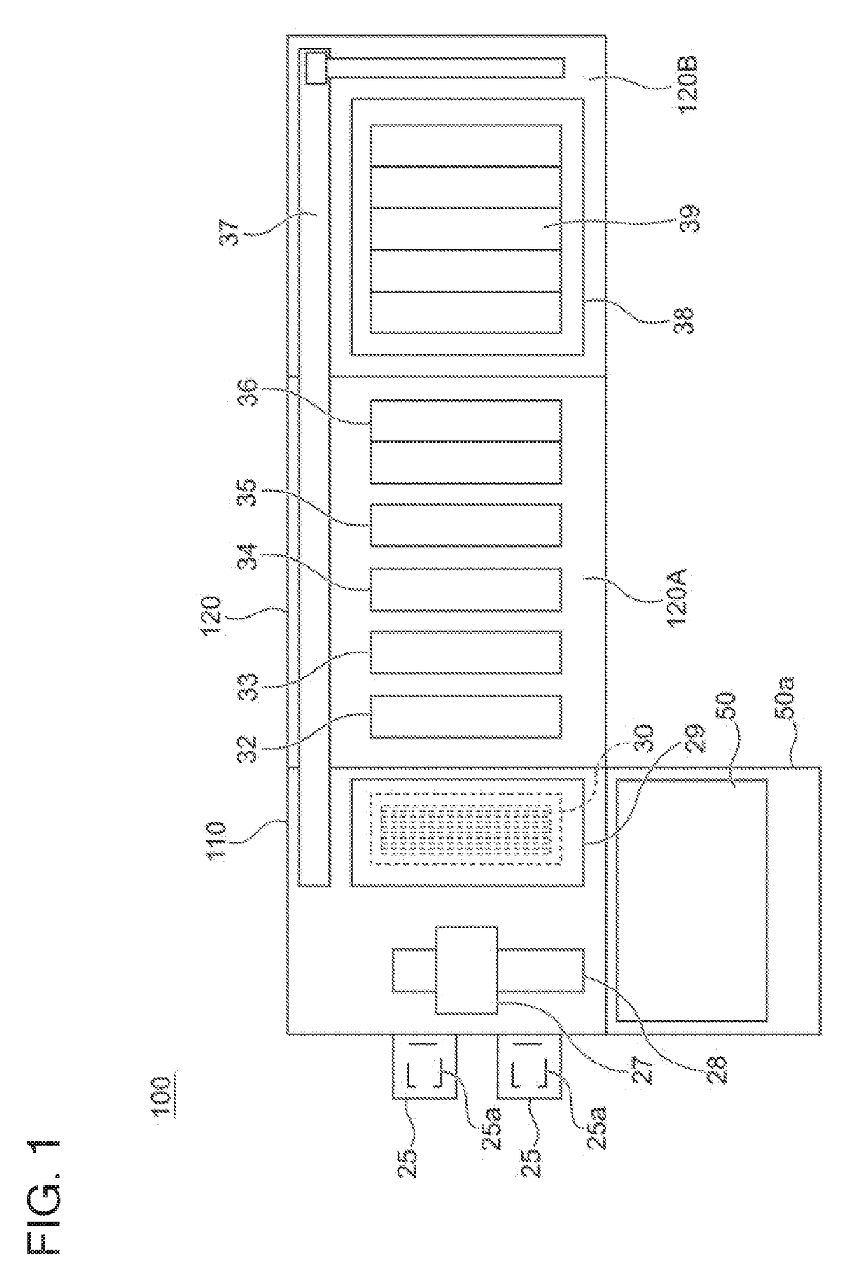
[0016]The following describes embodiments of the present invention with reference to the accompanying drawings. In the drawings to be described below, any identical or equivalent components are denoted by an identical reference sign, and duplicate description thereof will be omitted. FIG. 1 is an entire layout diagram of a plating apparatus including a cleaning apparatus according to the present embodiment. As illustrated in FIG. 1, this plating apparatus 100 mainly includes a loading / unloading unit 110 configured to load a substrate (corresponding to an exemplary target object) onto a substrate holder and unload the substrate from the substrate holder, a processing unit 120 configured to process the substrate, and a cleaning part 50a. The processing unit 120 includes a preprocessing-postprocessing unit 120A configured to perform preprocessing and postprocessing on the substrate, and a plating processing unit 120B configured to perform plating processing on the substrate. Substrates...


PUM

PropertyMeasurementUnit
diameteraaaaaaaaaa
sizeaaaaaaaaaa
stiffnessaaaaaaaaaa

Abstract

A cleaning apparatus is provided. This cleaning apparatus includes an inlet, an outlet, a first conveyance path, a second conveyance path, a cleaning unit disposed on the first conveyance path and configured to clean the target object in a non-contacting manner, and a drying unit disposed on the first conveyance path and configured to dry the target object in a non-contacting manner. The first conveyance path and the second conveyance path are vertically arranged side by side. The second conveyance path is positioned above the first conveyance path and connected with the outlet at an end point. The second conveyance path functions as a stocker configured to temporarily store the target object.

Description

CROSS-REFERENCE TO RELATED APPLICATION[0001]This application is based upon and claims benefit of priority from Japanese Patent Application No. 2016-127630 filed on Jun. 28, 2016 and Japanese Patent Application No. 2016-133933 filed on Jun. 28, 2016, the entire contents of which are incorporated herein by reference.BACKGROUND OF THE INVENTIONField of the Invention[0002]The present invention relates to a cleaning apparatus, a plating apparatus using the same, and a cleaning method.Description of the Related Art[0003]It has been a conventional practice to form wires and bumps (protruded electrodes) on the surface of a substrate such as a semiconductor wafer or a printed board. This formation of wires, bumps, and the like has been performed by a known method called an electrolytic plating.[0004]A plating apparatus used in the electrolytic plating performs plating processing on a circular substrate such as a wafer typically having a diameter of 300 mm. In addition to such a circular subs...

Claims


Application Information

Patent Timeline
Patent Type & Authority Applications(United States)
IPC IPC(8): C25D17/00H01L21/02B08B5/02B08B3/04C25D21/08B08B3/02H01L21/288
CPCC25D17/001C25D21/08B08B5/023H01L21/2885B08B3/04H01L21/02068B08B3/022H01L21/02057H01L21/67028H01L21/67051H01L21/67161H05K3/0085H05K3/26H05K2203/075H01L21/02046H01L21/02052H01L21/67034H01L21/6723H01L21/67754H01L21/67772
Inventor YAMAKAWA, JUNITSU
Owner EBARA CORP
Why Eureka
Try Eureka