Low latency decoding in multi-input multi-output radar

a multi-input, multi-output technology, applied in the field of low latency decoding of multi-input multi-output radars, can solve the problems that the decoding delay can affect the information obtained from reflections

Active Publication Date: 2017-12-28
GM GLOBAL TECH OPERATIONS LLC
View PDF3 Cites 12 Cited by
  • Summary
  • Abstract
  • Description
  • Claims
  • Application Information

AI Technical Summary

Problems solved by technology

This latency in the decoding can affect the information obtained from the reflections.

Method used


Image

  • Low latency decoding in multi-input multi-output radar
  • Low latency decoding in multi-input multi-output radar
  • Low latency decoding in multi-input multi-output radar

Examples


Embodiment Construction

[0011]The following description is merely exemplary in nature and is not intended to limit the present disclosure, its application or uses. It should be understood that throughout the drawings, corresponding reference numerals indicate like or corresponding parts and features.

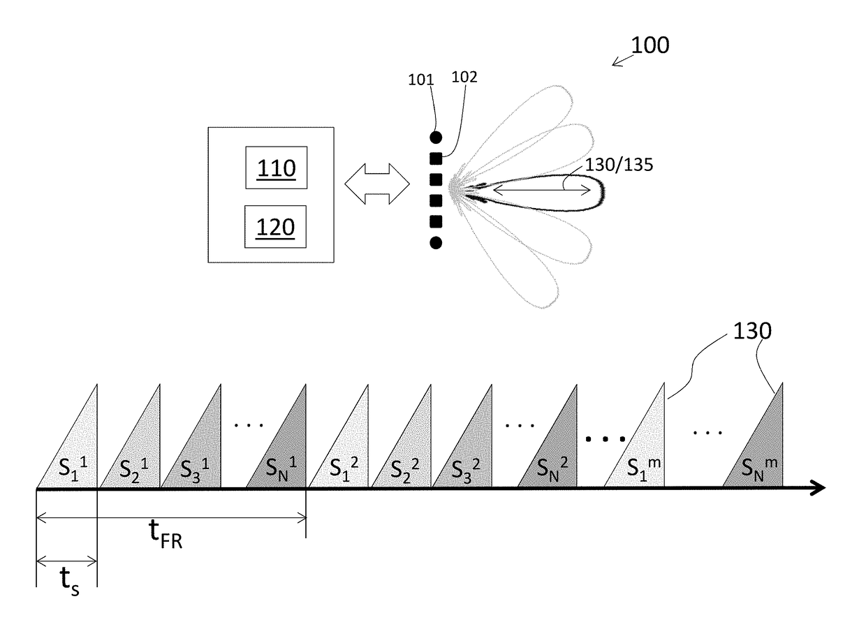
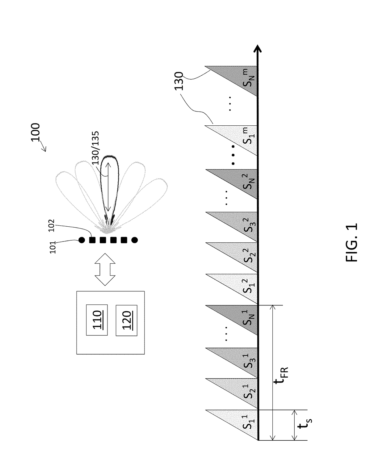
[0012]As previously noted, code-based MIMO radar facilitates resolving which transmitters are associated with each received reflection at each receive element. The code-based MIMO radar according to embodiments herein is a linear frequency-modulated continuous wave (LFM-CW) MIMO system. Each LFM-CW signal exhibits a different linear increase (or decrease) in frequency over the duration of the continuous wave and is referred to as a chirp. The total time duration to transmit a chirp from every transmitter is referred to as the frame duration. Generally, the reflections resulting from each of the transmissions are received and decoded together. Accordingly, while the maximum detectable range is directly proportio...


PUM


Abstract

A multi-input multi-output (MIMO) radar system and method of performing low-latency decoding in a MIMO radar system. The method includes transmitting a different linear frequency-modulated continuous wave (LFM-CW) transmit signal from each of N transmit elements of the MIMO radar system, each transmit signal associated with teach of the N transmit elements including a respective code, and receiving reflections associated with each of the transmit signals from each of the N transmit elements at each receive element of the MIMO radar system. Processing each symbol corresponding with each received reflection on a symbol-by-symbol basis is done to obtain a respective decoded signal prior to receiving all the received reflections associated with all the N transmit elements, wherein the processing includes using a Hadamard matrix with N columns in which each column is associated with the respective code transmitted by each of the N transmit elements.

Description

FIELD OF THE INVENTION[0001]The subject invention relates to low latency decoding in multi-input multi-output (MIMO) radar.BACKGROUND[0002]In a MIMO radar system, multiple co-located transmit antennas radiate and multiple receiver antennas each receive the resulting reflections associated with all the transmit antennas. For a MIMO radar system with N transmitters and K receivers, the virtual field of view is N*K. This increased virtual field of view (in comparison with the real field of view of N+K) facilitates increased spatial resolution with fewer antenna elements. Because each receiver receives reflections associated with every transmitter, the reflections at each receiver must be resolved. Transmission according to a time division multiple access (TDMA) scheme is one way to resolve the transmissions, but the maximum detectable velocity of a target may be reduced due to the time between transmissions according to the TDMA scheme. Another way to resolve the transmissions is by us...

Claims


Application Information

Patent Timeline
Patent Type & Authority Applications(United States)
IPC IPC(8): G01S13/02G01S13/93G01S13/931
CPCG01S13/931G01S13/0209G01S13/325G01S13/343G01S13/867G01S2013/93271
Inventor POKRASS, ALEXANDERBILIK, IGALVILLEVAL, SHAHAR
Owner GM GLOBAL TECH OPERATIONS LLC
Why Eureka
Try Eureka