Rotor life estimation device and vacuum pump

a technology of life estimation and vacuum pump, which is applied in the direction of force measurement using piezo-resistive materials, testing/monitoring control systems, instruments, etc., can solve the problem that the timing of pump operation cannot be grasped in advance, the speed of creep deformation cannot be ignored, and the life becomes extremely high

Active Publication Date: 2017-12-28
SHIMADZU CORP
View PDF2 Cites 6 Cited by
  • Summary
  • Abstract
  • Description
  • Claims
  • Application Information

AI Technical Summary

Benefits of technology

[0010]The data processing section performs averaging processing of reducing the number of the plurality of data sets stored in the storage section, and newly stores data sets in a free space of the data storage area generated by the averaging processing.

Problems solved by technology

That is, the speed of creep deformation cannot be ignored.
However, the vacuum pump described in Patent Literature 1 is configured such that pump operation is stopped at the timing at which a rotor damage risk due to a creep life becomes extremely high, and the timing at which pump operation is stopped cannot be grasped in advance.
For this reason, preparation for rotor maintenance cannot be performed in advance, leading to a difficulty in smooth maintenance.

Method used


Image

  • Rotor life estimation device and vacuum pump
  • Rotor life estimation device and vacuum pump
  • Rotor life estimation device and vacuum pump

Examples


first embodiment

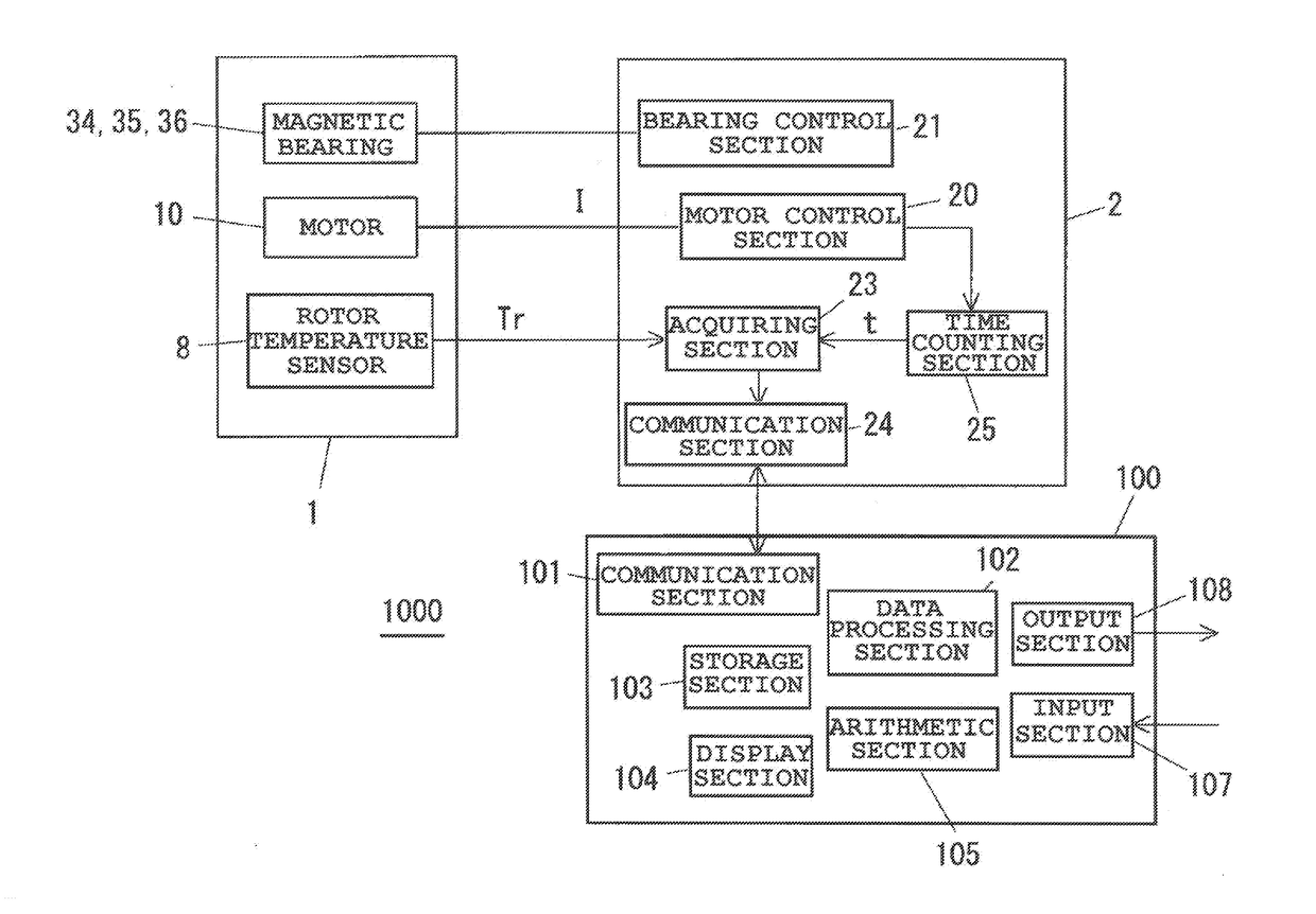
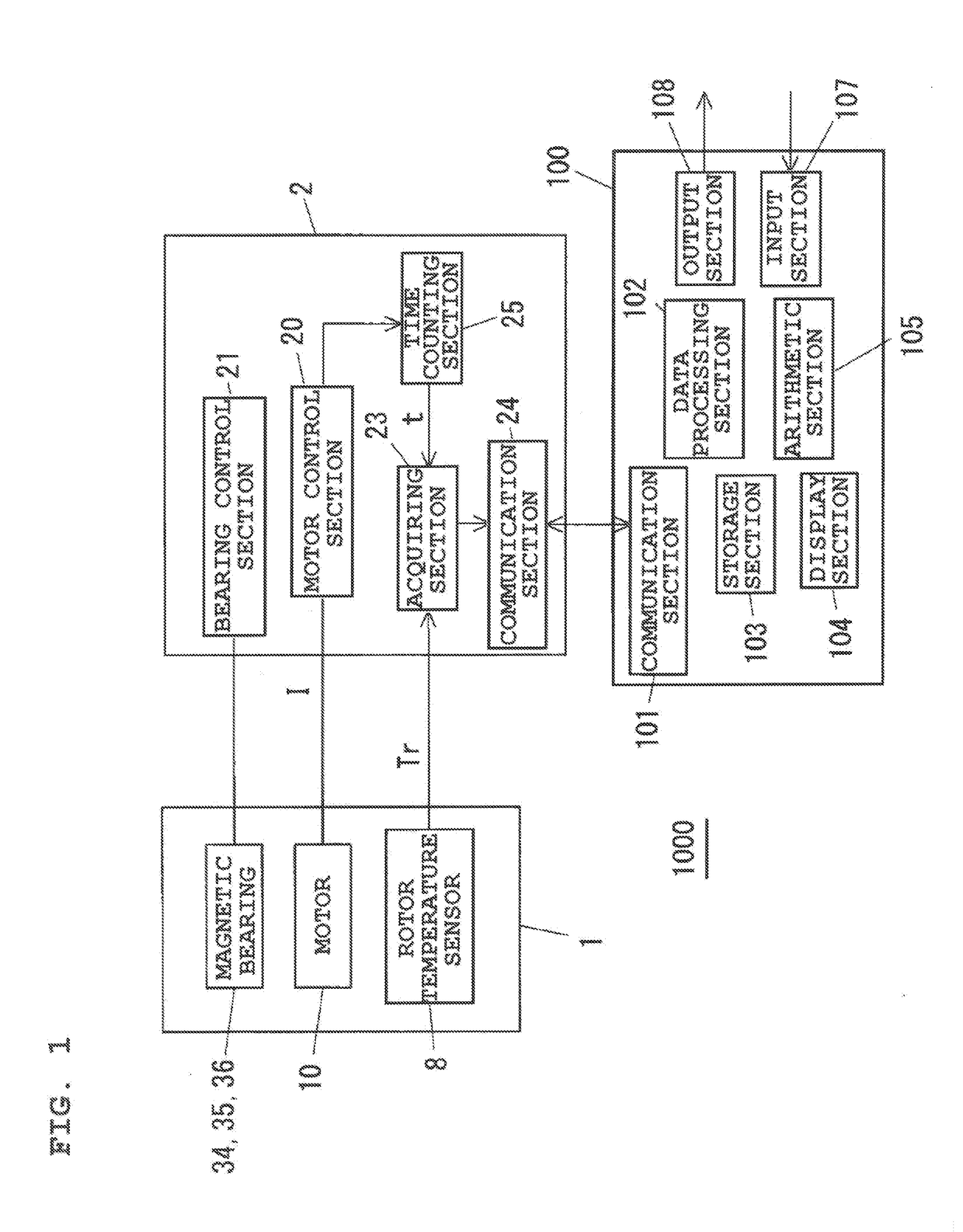
[0035]FIG. 1 is a block diagram of an outline configuration of a vacuum pump 1000. The vacuum pump 1000 includes a pump main body 1, a control unit 2 configured to drive and control the pump main body 1, and a rotor life estimation device 100. A magnetic bearing turbo-molecular pump will be described as an example in the present embodiment, but the present invention is not limited to the turbo-molecular pump as long as the pump is a vacuum pump including a rotor configured to rotate at high speed.

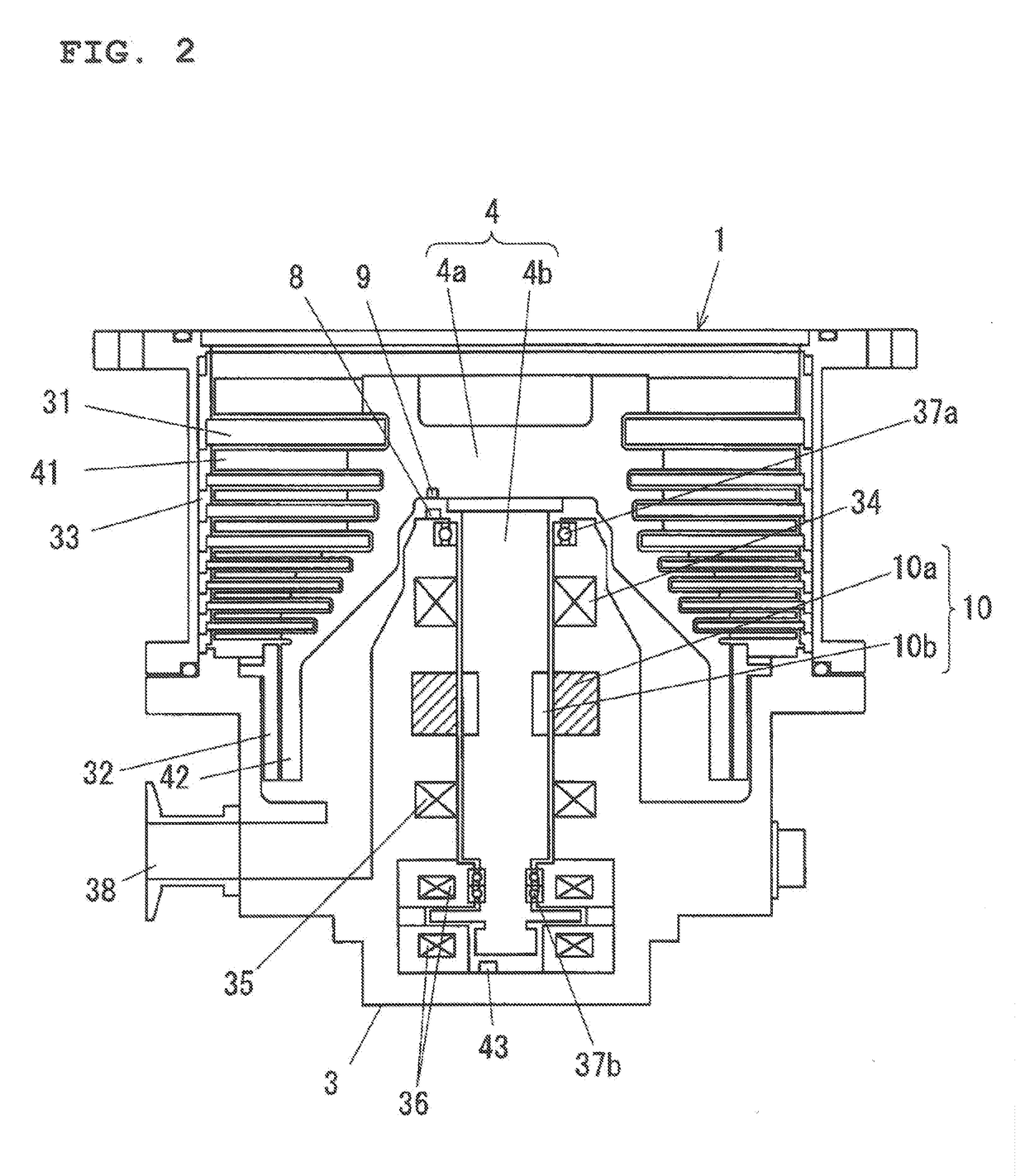
[0036]FIG. 2 is a cross-sectional view of an example of the pump main body 1. The pump main body 1 includes a turbo pump stage having rotor blades 41 and stationary blades 31, and a screw groove pump stage having a cylindrical portion 42 and a stator 32. In the screw groove pump stage, a screw groove is formed at the stator 32 or the cylindrical portion 42. The rotor blades 41 and the cylindrical portion 42 are formed at a pump rotor 4a. The pump rotor 4a is fastened to a shaft 4b. The pump...

second embodiment

[0100]In the above-described first embodiment, the life is estimated using the acquired integrated strain value. However, in a second embodiment, the amount of strain of a pump rotor 4a in an overhaul of a vacuum pump is actually measured, and a rotor life is estimated based on the actually-measured strain amount.

[0101]In a turbo-molecular pump used in an etching process for use application of a semiconductor FPD, a reactive product is easily deposited, and for this reason, the overhaul operation of cleansing and removing the deposited substance is typically performed on a regular basis. Thus, in the present embodiment, the strain of the pump rotor 4a is actually measured at the timing of the overhaul, and the rotor life is estimated using such actual measurement data.

[0102]For example, as shown in FIG. 5, the overhaul is performed at each of cumulative rotor drive times to1, to2, to3, to4. Then, the dimensions of the pump rotor 4a are measured at each of the time of initial assembl...

third embodiment

[0116]A third embodiment is a combination of the above-described first and second embodiments, and is configured such that an integrated strain value is corrected by permanent strain εpn actually measured in an overhaul. FIG. 15 is a graph for describing the third embodiment, and a curve L10 is a curve representing the integrated strain value Ld shown in FIG. 9. The integrated strain value Ld is set as one when permanent strain εp reaches strain (life strain) upon a lapse of a rotor life. Thus, (Permanent Strain εp) / (Life Strain) corresponds to the integrated strain value Ld.

[0117]As described above, in a first overhaul, an inner-diameter dimension d is actually measured such that an actual measurement value of permanent strain εp1 caused until the first overhaul after assembly is acquired. A mark P30 represents (Permanent Strain εp1) / (Life Strain) for the permanent strain εp1 actually measured in the first overhaul. In an example shown in FIG. 15, there is a gap of ΔLε between the ...


PUM

PropertyMeasurementUnit
temperatureaaaaaaaaaa
rotor temperaturesaaaaaaaaaa

Abstract

A rotor life estimation device of a vacuum pump including a rotor rotatably driven by a motor and a rotor temperature detection section configured to detect a temperature of the rotor, comprises: an arithmetic section configured to calculate a strain equivalent corresponding to creep strain of the rotor based on a correlation between a creep strain speed equivalent and the temperature of the rotor and the temperature detected by the rotor temperature detection section; an estimation section configured to estimate a rotor life based on the calculated strain equivalent; and a providing section configured to provide information on the estimated rotor life.

Description

BACKGROUND OF THE INVENTION1. Technical Field[0001]The present invention relates to a rotor life estimation device and a vacuum pump.2. Background Art[0002]In a turbo-molecular pump, a rotor is made of an aluminum material, and therefore, a relatively-low acceptable temperature unique to the aluminum material is exhibited. Typically, in a high-speed rotation state in which the turbo-molecular pump exerts an exhaust effect, the rotor is in a high tensile stress state due to a high centrifugal force effect. In the tensile stress state, when a rotor temperature reaches equal to or higher than an acceptable temperature (e.g., 120° C.), permanent strain rapidly increases. That is, the speed of creep deformation cannot be ignored. For this reason, operation is made at a temperature lower than the acceptable temperature.[0003]Conversely, when operation is continued at a temperature of equal to or higher than the acceptable temperature, creep strain of the rotor increases, and the dimension...

Claims


Application Information

Patent Timeline
Patent Type & Authority Applications(United States)
IPC IPC(8): G05B23/02G01L1/18G01K13/08F04D19/04F04D29/26
CPCG05B23/0283G01L1/18F04D29/26F04D19/04G01K13/08F04D27/001F05D2270/303
Inventor KOZAKI, JUNICHIRO
Owner SHIMADZU CORP
Why Eureka
Try Eureka