Brake modulator for a compressed air braking system of a vehicle

Active Publication Date: 2018-01-04
ZF CV SYST EURO BV
View PDF0 Cites 5 Cited by
  • Summary
  • Abstract
  • Description
  • Claims
  • Application Information

AI Technical Summary

Benefits of technology

The present invention provides a brake modulator for a compressed air braking system that is reliable and affordable. The brake modulator includes a guide body insert that can be easily inserted into the main housing of the system, resulting in a simplified and cost-effective manufacturing process. The guide body insert has symmetrically arranged relay valves that ensure a symmetrical pressure configuration and uniform pressure build-up to both sides. The valve piston is also guided and secured in a simple and affordable manner. The overall design of the brake modulator reduces the need for additional machining and enables efficient assembly.

Problems solved by technology

It is found, however, that such a construction, with the compressed air connection provided transversely, gives rise to a complex shaping of the main housing.
Furthermore, the compressed air ports are typically provided from opposite sides and are axially offset from one another; such a pneumatic supply is, however, generally asymmetrical with respect to the relay valves, so that the relay valves may in some cases exhibit a non-uniform pressure build-up.

Method used


Image

  • Brake modulator for a compressed air braking system of a vehicle
  • Brake modulator for a compressed air braking system of a vehicle
  • Brake modulator for a compressed air braking system of a vehicle

Examples


Embodiment Construction

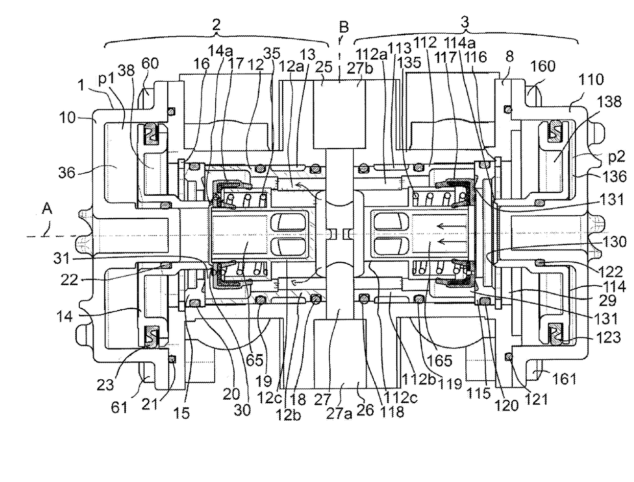
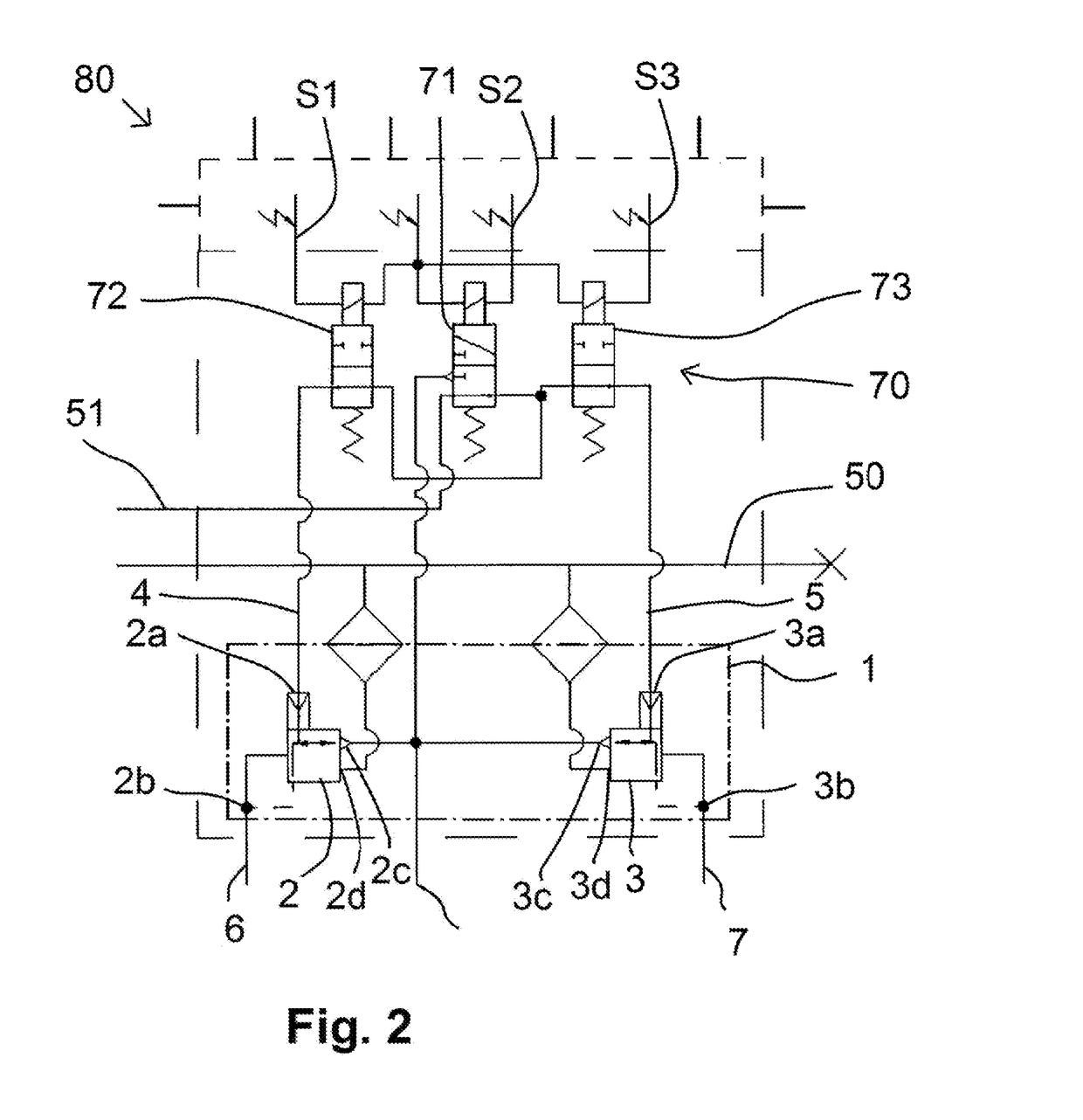
[0021]With reference to the specific embodiment of the Figures, wherein like numerals generally indicate like parts throughout the several views, a brake modulator is shown at 1. The brake modulator 1 serves as an ABS brake modulator 1 and has the functionality of two pneumatically activated relay valves 2 and 3, of which a first relay valve 2 has a pneumatic control pressure inlet 2a connected to a pneumatic control pressure line 4, together with a compressed air outlet 2b to which a brake line 6 is connected, and a vent 2c; correspondingly, a second relay valve 3 has a pneumatic control inlet 3a to which a pneumatic control line 5 is connected, together with a compressed air outlet 3b to a brake line 7, and a vent 3c.

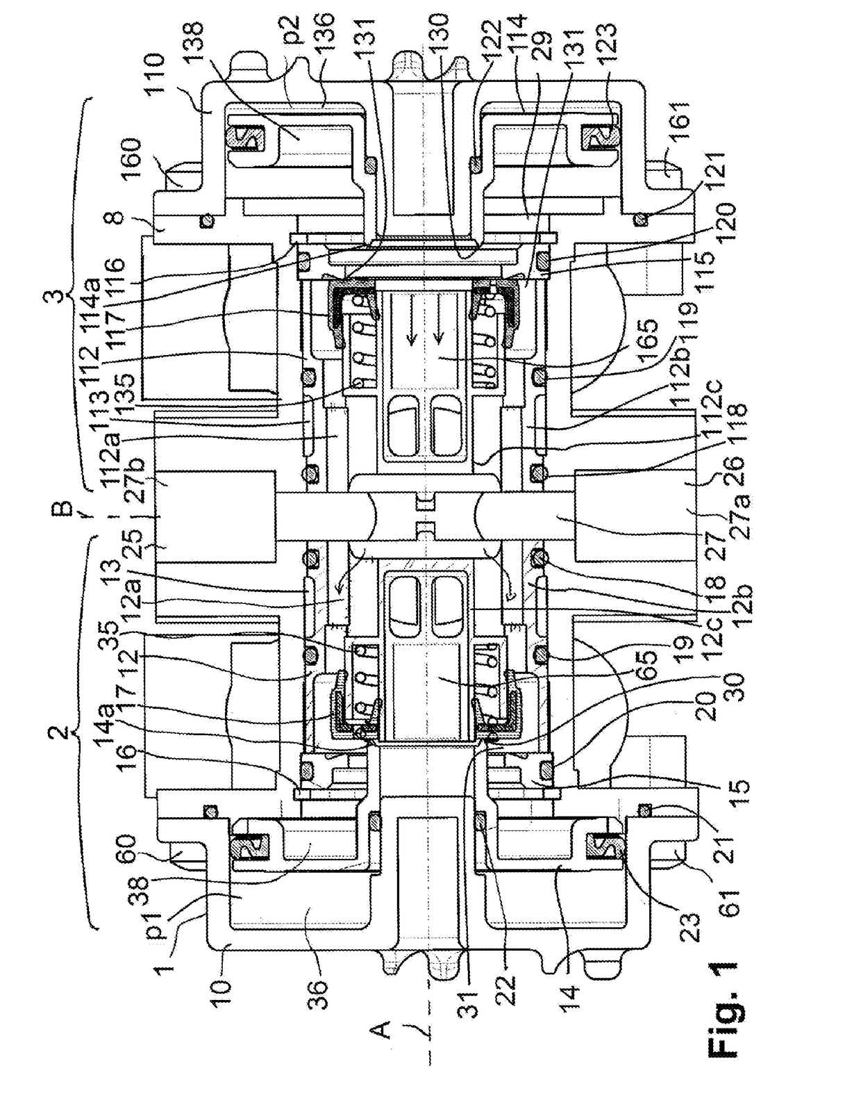
[0022]In its structure as shown in FIG. 1, the brake modulator 1 comprises a main housing 8, a first cover 10 as part of the first relay valve 2, and a second cover 110 as part of the second relay valve 3. In the further description the reference symbols of the eleme...


PUM


Abstract

A brake modulator (1) for a compressed air braking system (80) of a vehicle is disclosed. The brake modulator (1) has a main housing (8) and two relay valves (2, 3) Each relay valve is configured with a delivery valve seat (31, 131) and a vent valve seat (30, 130) and a vent position, wherein compressed air inlets (2d, 3d) are connected via a transverse bore (27) to a common compressed air inlet port (25, 26), and a delivery duct (12a, 112a) extends in the axial direction (A) in each relay valve (2, 3) The relay valves (2, 3) have guide body inserts (12, 112) which are inserted into a longitudinal bore (29) of the main housing (8), which longitudinal bore (29) extends in the axial direction (A), and the relay valves (2, 3) in each case have the delivery duct (12a, 112a).

Description

CROSS-REFERENCE TO RELATED APPLICATIONS[0001]This application is the National Stage of International Application No. PCT / EP2016 / 000049, filed on 13 Jan. 2016, which claims priority to and all advantages of German Patent Application No. 10 2015 000 763.7, filed on 22 Jan. 2015, the content of which is hereby incorporated by reference.FIELD OF THE INVENTION[0002]The invention generally relates to a brake modulator and, more specifically, to a brake modulator for a compressed air braking system of a vehicle.BACKGROUND OF THE INVENTION[0003]The installation of a brake modulator varies internationally according to different systems and standards, with both a direct connection to a compressed air reservoir and a connection via a pneumatic line being known. It is therefore advantageous to equip the brake modulator with two compressed air ports, both of which serve as compressed air inlets for relay valves. The redundant compressed air port may be closed, for example, by a plug, although co...

Claims


Application Information

Patent Timeline
IPC IPC(8): B60T8/38B60T8/34B60T13/26B60T15/18
CPCB60T8/38B60T8/342B60T15/182B60T13/26
Inventor LUCHAU, KARSTEN-WILHELMSIEKER, ARMINSTEPHAN, ARNEWICHMANN, OLAF
Owner ZF CV SYST EURO BV
Why Eureka
Try Eureka