Cooling system for unmanned aerial vehicle

a technology for unmanned aerial vehicles and cooling systems, which is applied in the direction of mechanical equipment, machines/engines, transportation and packaging, etc., can solve the problems of affecting the normal operation affecting the service life of unmanned aerial vehicles, and damage to unmanned aerial vehicles

Inactive Publication Date: 2018-01-04
YUNEEC INT (CHINA) CO LTD
View PDF2 Cites 37 Cited by
  • Summary
  • Abstract
  • Description
  • Claims
  • Application Information

AI Technical Summary

Benefits of technology

[0006]An object of the present invention is to provide a cooling system for unmanned aerial vehicle, which is able to cool down the whole vehicle.

Problems solved by technology

If not being timely cooling down, the heat affects the normal operation of the unmanned aerial vehicle.
Prolonged overheating damages the unmanned aerial vehicle or compromises the service life of the unmanned aerial vehicle.
Other components of the unmanned aerial vehicle, such as the motor and the chip, also generate a large amount of heat.
The conventional cooling air guide components are not able to guarantee the cooling effect.
Besides, the air guide holes are not able to collect the air sufficiently to cool down the vehicle due to the disposed position and structure of the air guide holes.
The space inside the unmanned aerial vehicle is limited, to dispose a fan in which requires enlarging the main body of the unmanned aerial vehicle and increases the weight of the vehicle.
Furthermore, the fans generate considerable noise while working.

Method used


Image

  • Cooling system for unmanned aerial vehicle
  • Cooling system for unmanned aerial vehicle
  • Cooling system for unmanned aerial vehicle

Examples


Embodiment Construction

[0039]Referring to the drawings, according to a preferred embodiment of the present invention, the object, characteristics and advantages of the present invention is clearly illustrated.

[0040]Specific details are described in the embodiments of the present invention for a better understanding. Other embodiments of the present invention are able to be conceived. One skilled in the art will understand that the embodiment of the present invention as shown in the drawings and described above is exemplary only and not intended to be limiting.

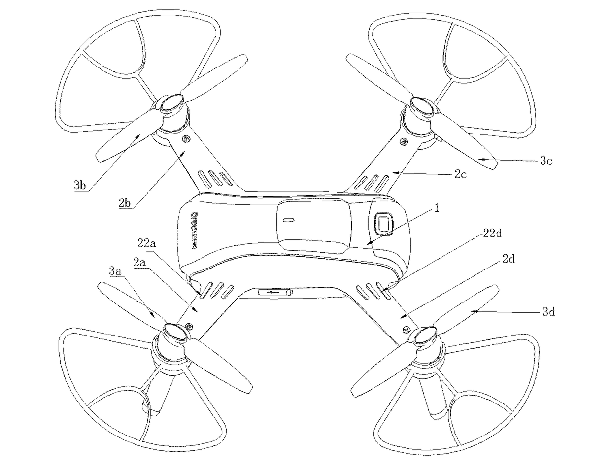
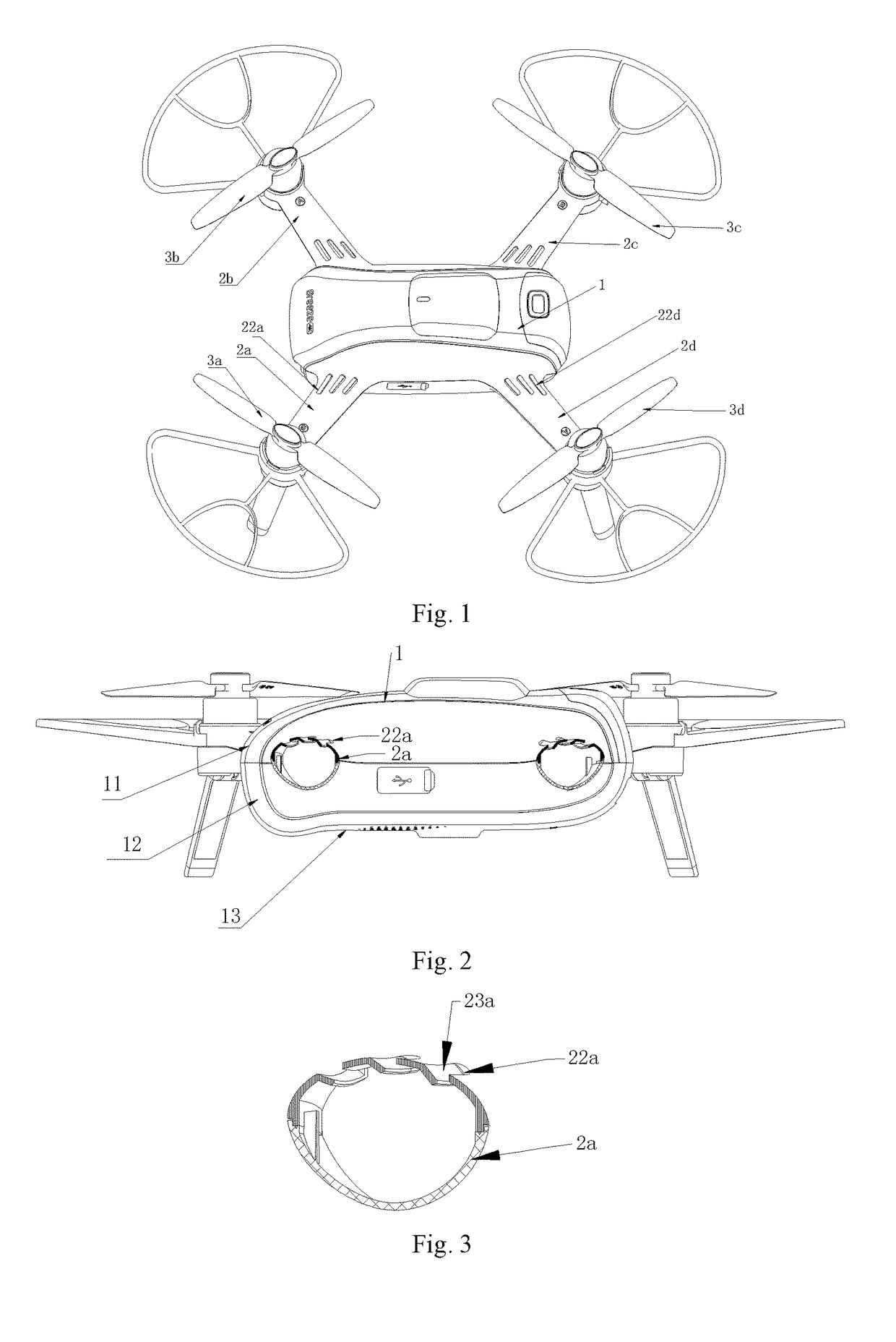
[0041]Referring to FIG. 1, according to an embodiment of the present invention, a cooling system for an unmanned aerial vehicle comprises main body 1, four arms 2a, 2b, 2c, and 2d disposed on the main body 1, two clockwise rotating propellers 3a and 3c and two counterclockwise rotating propellers 3b and 3d which are disposed on the arms respectively.

[0042]The propeller is driven by the motor to rotate. The rotating direction is controlled by a contro...


PUM


Abstract

The present invention disclosed a cooling system for unmanned aerial vehicle, which includes a main body, four arms disposed on the main body, two clockwise rotating propellers and two counterclockwise rotating propellers disposed on the arms respectively; wherein at least one air guide hole on each of the arms, which guide air to a middle of the main body; the two clockwise rotating propellers are disposed diagonally and the two counterclockwise rotating propellers are disposed diagonally; a clockwise rotating propeller is on a left-front arm; each of the clockwise and the counterclockwise rotating propellers rotates to generate an airstream which is configured to sweep towards the arm, the airstreams are configured to flow to an internal part of the main body by the air guide hole. The cooling system is able to cool down the whole unmanned aerial vehicle.

Description

CROSS REFERENCE OF RELATED APPLICATION[0001]The present invention claims priority under 35 U.S.C. 119(a-d) to CN 201621449454.8, filed Dec. 27, 2016; CN 201621449383.1, filed Dec. 27, 2016; and CN 201611230997.5, filed Dec. 27, 2016.BACKGROUND OF THE PRESENT INVENTIONField of Invention[0002]The present invention relates to the unmanned aerial vehicle field, and more particularly to a cooling system for unmanned aerial vehicle.Description of Related Arts[0003]An unmanned aerial vehicle is a vehicle without a person on board, which is operated by the radio remote control apparatus and on-board preset control devices. Heat is generated and accumulates while the unmanned aerial vehicle is working. If not being timely cooling down, the heat affects the normal operation of the unmanned aerial vehicle. Prolonged overheating damages the unmanned aerial vehicle or compromises the service life of the unmanned aerial vehicle. Conventionally, a cooling part is disposed on the unmanned aerial ve...

Claims


Application Information

Patent Timeline
Patent Type & Authority Applications(United States)
IPC IPC(8): B64D13/00F01P5/02B64C39/02F01P1/06
CPCB64D13/006F01P1/06F01P5/02F01P2050/20B64C2201/042B64C2201/108B64C2201/165B64C39/024B64D33/08B64U50/19B64U30/20B64U50/13
Inventor TIAN, YUJIANG, WENYAN
Owner YUNEEC INT (CHINA) CO LTD
Why Eureka
Try Eureka