Head mounted projection display with multilayer beam splitter and color correction

a projection display and beam splitter technology, applied in the field of headmounted projection displays, can solve the problems of poor brightness or image quality, hmpd extending too far from the user's face, poor brightness, etc., and achieve the effect of high transmission of returning light and maximum transmission of returning ligh

Active Publication Date: 2018-01-04
TILT FIVE INC
View PDF7 Cites 15 Cited by
  • Summary
  • Abstract
  • Description
  • Claims
  • Application Information

AI Technical Summary

Benefits of technology

[0012]A polarizing beam splitter is disclosed that is a multilayer stack of a polarizing beam splitter and at least one other optical layer to optimize an initial reflection of projected light towards a retroreflector and maximize transmission of returning light. In one embodiment, a polarizing beam splitter stack includes a polarizing beam splitter with a phase retarder layer, or waveplate. The stack may, for example, be formed as a film attached or bonded to the polarizing beam splitter. The phase retarder layer may be a quarter wave film. The multilayer beam splitter stack may be utilized to achieve a maximum reflection of projected light exiting a head mounted display, such as a head mounted projection display (HMPD). The quarter wave film may be used to achieve a high transmission of returning light.
[0013]In one embodiment, the polarizing beam splitter stack is designed such that circularly polarized light of a specific handedness (left or right) will be reflected as light of circular polarization, and then after retroreflection, the light will pass back through the multilayer beam splitter to enter a user's eye as plane polarized light. In one embodiment, a circularly polarized projector is used and may be positioned in front of the multilayer structure. Additionally, in one embodiment, orthogonal polarization may be used for each of the user's eyes to provide for stereoscopic isolation of stereoscopic images without added filtering.
[0014]Furthermore, in one embodiment, a HMPD system used in augmented reality applications has real-time information relating the position and orientation (pose) of the projector with regard to a retroreflective surface that is returning the projected image back to the eyes of the user. Based on that real-time information and calibration information regarding the optical characterization of the retroreflective surface, an adjustment is made to the intensities of the primary colors of the projected pixels based on calculating the incidence angle of each pixel, so as to compensate for image distortion due to imperfect headset optics and imperfect retroreflection.

Problems solved by technology

A general problem with head mounted display technologies is obtaining a combination of high image quality, compact size, and a reasonable price point.
Many designs suffer from poor brightness or image quality issues.
Many of these approaches also suffer from one or more problems, including the HMPD extending too far out from the user's face, poor brightness, poor image quality, or high cost.
It is also difficult in a HMPD to simultaneously obtained a combination of low extension, high brightness, and high image quality.
However, the approach of FIG. 1 results in significant loss of brightness, and therefore image contrast, at each pass on / through the beam splitter.
However, a disadvantage of the positioning of the waveplate is that it causes an unwanted extension of the front of the head mounted unit.
In a commercial product the optics have to be comparatively rugged and cheap to manufacture and thus there are practical limitations on how closely optical components can be placed.
As a result, the total forward extension is unacceptable for many consumer applications.
This increases the cost of the HMPD.
Also, not all rays in the projected Field of View (FoV) will strike the waveplate at an orthogonal angle of incidence which can result in imperfect phase retardation and chromatic distortions.
These effects also reduce the image quality of the images that make it to the user's eyes.

Method used


Image

  • Head mounted projection display with multilayer beam splitter and color correction
  • Head mounted projection display with multilayer beam splitter and color correction
  • Head mounted projection display with multilayer beam splitter and color correction

Examples


Embodiment Construction

[0040]Embodiments of the present invention are generally related to improvements in head mounted projection displays (HMPDs), although one of ordinary skill in the art would understand that there are other applications as well. This includes HMPDs in which a beam splitter is used to direct projected light out of the HMPD and receive returning light.

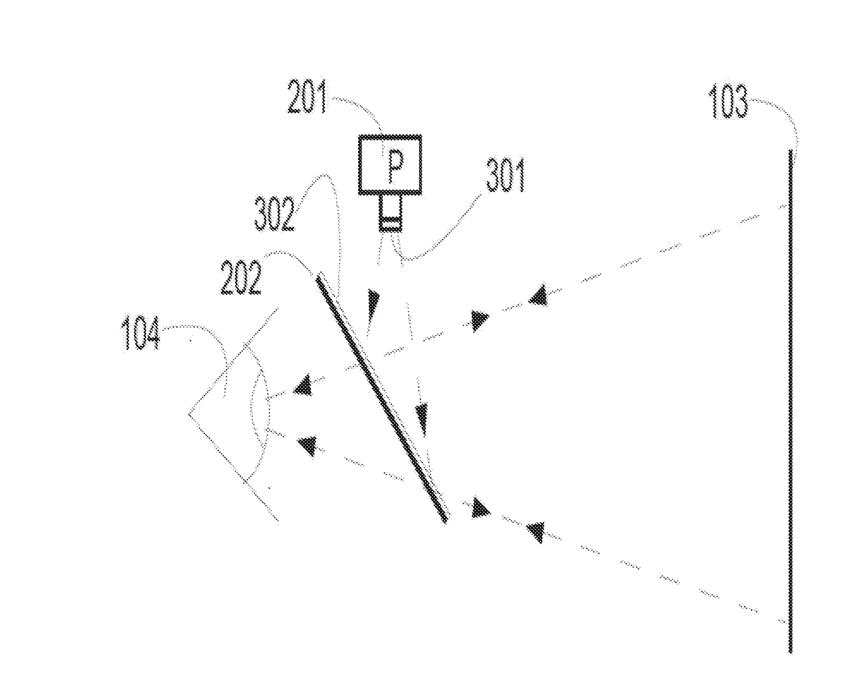
[0041]FIG. 3A shows an embodiment in which the projector 201 of a HMPD has its plane polarized (P in projector 201) output changed to circular polarization by a quarter waveplate optical retarder 301. The circularly polarized light passing through quarter waveplate optical retarder 301 then encounters another quarter wave retarding film 302 that has been placed (stacked-up) on the face of the polarizing beam splitter 202 with fast and slow axes orientated 45° with respect to the plane polarization axis of polarizing beam splitter 202. The quarter wave retarding film 302 may be stacked on the face of the polarizing beam splitter by, for ex...


PUM


Abstract

A head mounted projection display includes a polarizing beam splitter stack that includes a waveplate. The polarizing beam splitter stack reduces optical losses and has a low forward extension. The polarizing beam splitter may be used at a 45 degree angle or at a non 45 degree angle relative to the line of view. A correction may be also be performed to the intensity of individual pixels to account for chromatic non-uniformity in the optical response of a retroreflector and other optical components.

Description

CROSS REFERENCE TO RELATED APPLICATIONS[0001]This application claims the benefits of U.S. provisional patent application Ser. No. 62 / 357,842 filed Jul. 1, 2016, and U.S. provisional patent application Ser. No. 62 / 453,316 filed Feb. 1, 2017, each which are both incorporated in their entirety.FIELD OF THE INVENTION[0002]Embodiments of the present invention are generally related to the technology of head-mounted projection displays (HMPD) as used in virtual and augmented reality, and other computer graphics applications.BACKGROUND OF THE INVENTION[0003]There are a variety of different head mounted display technologies used for augmented reality and virtual reality applications. A general problem with head mounted display technologies is obtaining a combination of high image quality, compact size, and a reasonable price point. For example, many head mounted displays extend far out in front of a user's face. For example, some head mounted displays extend out ten centimeters or more from ...

Claims


Application Information

Patent Timeline
Patent Type & Authority Applications(United States)
IPC IPC(8): G02B27/28G02B27/01G02B27/42G02B17/08
CPCG02B27/283G02B27/4211G02B2027/011G02B17/0884G02B27/0101G02B2027/0156G02B27/0176G02B27/0172
Inventor RONG, WEICOONS, EVANELLSWORTH, JERI J.CLEMENTS, KEN
Owner TILT FIVE INC
Why Eureka
Try Eureka