
Gis based centralized fiber fault localization system

a fault localization and fiber network technology, applied in the direction of electrical equipment, transmission, electromagnetic transmission, etc., can solve the problems of affecting the adoption rate of fttp communication services, affecting the accuracy of fault location/position, and difficulty for technicians to locate/rectify the actual fault location/site, etc., to achieve accurate indication of exact location/position of faul

Active Publication Date: 2018-01-04
CENT FOR DEV OF TELEMATICS
View PDF16 Cites 13 Cited by
  • Summary
  • Abstract
  • Description
  • Claims
  • Application Information

AI Technical Summary

Benefits of technology

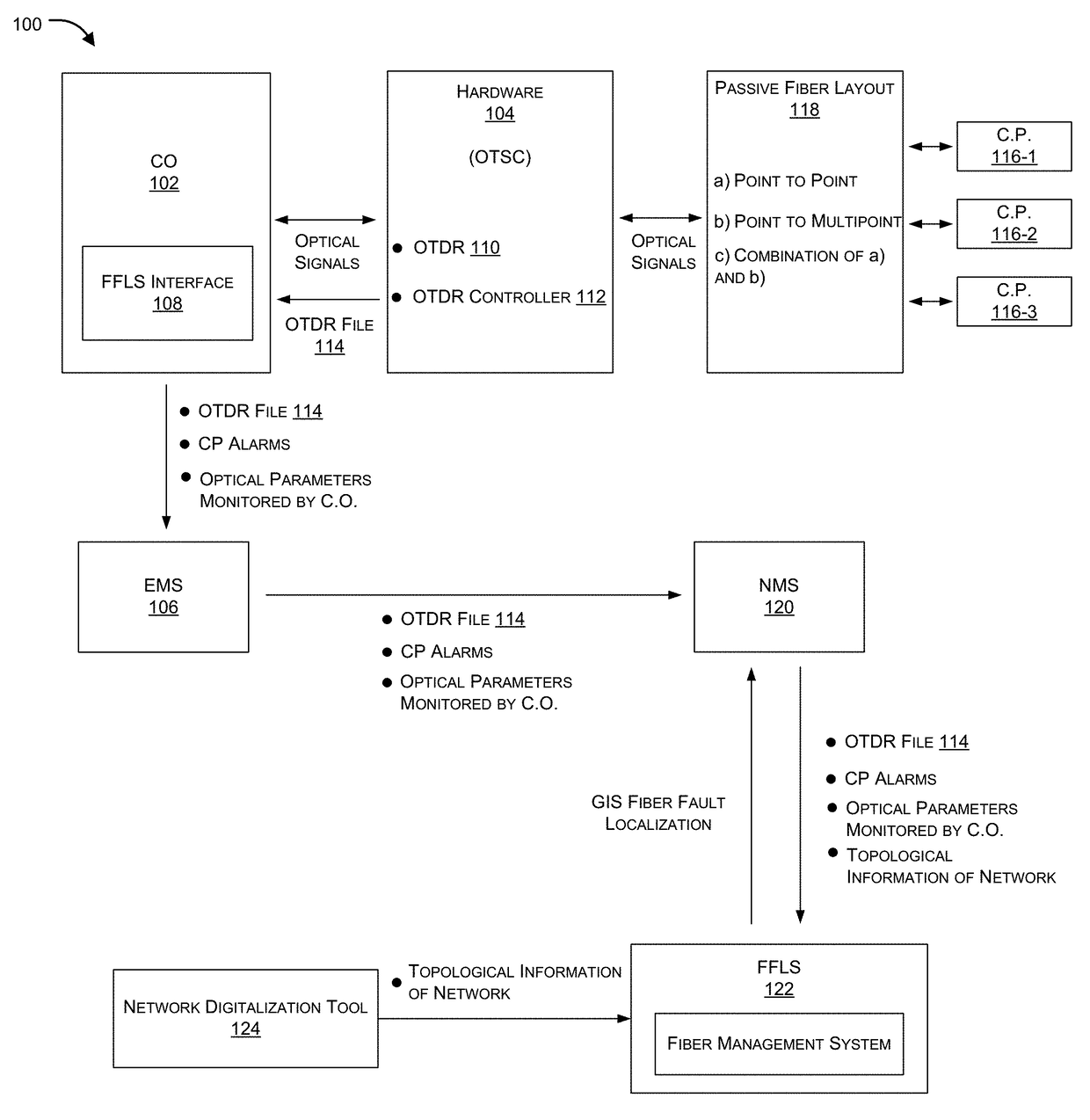
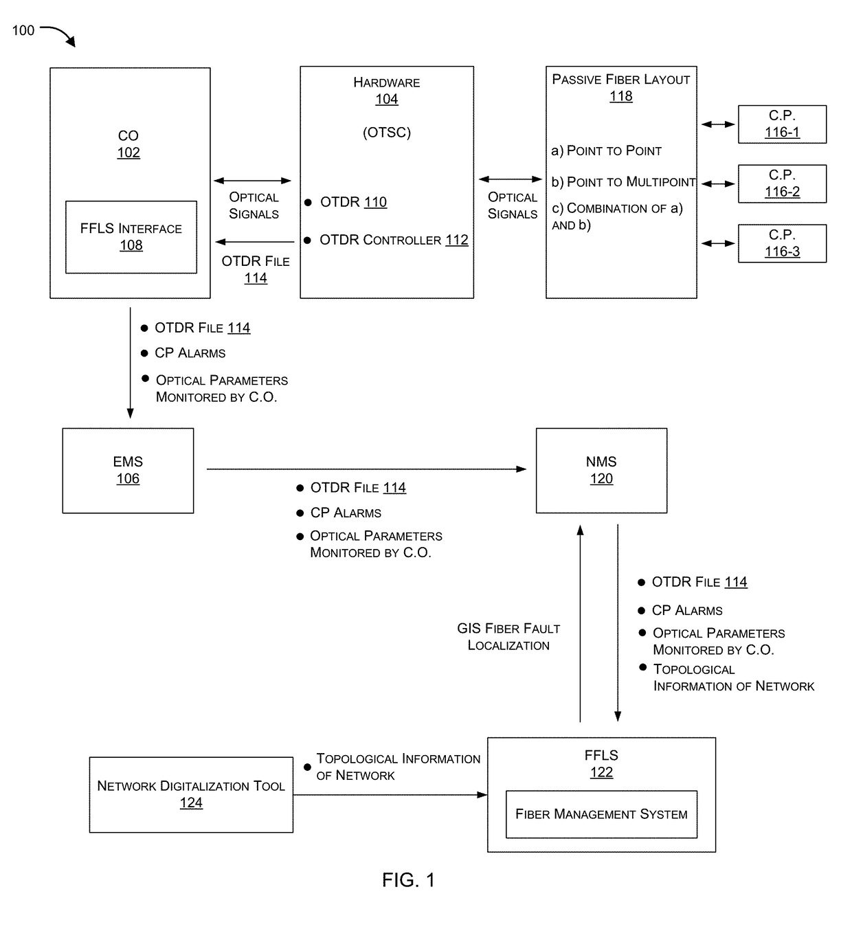
The present patent aims to provide an improved method for detecting precise fault location in fiber optic networks. It involves using an OTDR to measure abnormal reflections in the network, with an OTDR controller to manage the measurements. The OTDR reports the abnormality to the CO through an OTDR file. The CO processes the information and sends it to EMS, which sends it to NMS. The NMS processes the information and sends it back to the CO, which then sends it to FFLS server. The server processes the network topology information to issue GIS-based fiber fault localization information back to the NMS. This helps to accurately indicate the exact location of the fault. The NMS can also be operatively coupled with one or more OTDRs through the CO. Overall, this patent provides a more efficient, accurate, and quick way to detect fiber optic network faults.

Problems solved by technology

However, ongoing operation and maintenance expenses associated with the fiber plant also impact the adoption rate of FTTP communication services.
One such expense is the detection and finding location of fiber faults (e.g., a fiber cut, disconnection or breakage) that interrupt communication services.
However, existing OTDR based techniques require strong manual intervention every time a fault is reported, wherein a technician takes OTDR to the fiber location, identifies optical distance of the fault using the OTDR, and then maps the distance on the GIS map to determine the location, which due to difference in optical distance vs actual physical distance makes it difficult for the technician to locate / rectify the actual fault location / site.
A loss of signal may be a complete loss of communication with the CO or an unacceptable degradation of the communication link.
However, such brute-force approaches are prohibitively expensive.

Method used


Image

  • Gis based centralized fiber fault localization system
  • Gis based centralized fiber fault localization system
  • Gis based centralized fiber fault localization system

Examples


Embodiment Construction

[0020]The following is a detailed description of embodiments of the disclosure depicted in the accompanying drawings. The embodiments are in such detail as to clearly communicate the disclosure. However, the amount of detail offered is not intended to limit the anticipated variations of embodiments; on the contrary, the intention is to cover all modifications, equivalents, and alternatives falling within the spirit and scope of the present disclosure as defined by the appended claims.

[0021]Each of the appended claims defines a separate invention, which for infringement purposes is recognized as including equivalents to the various elements or limitations specified in the claims. Depending on the context, all references below to the “invention” may in some cases refer to certain specific embodiments only. In other cases it will be recognized that references to the “invention” will refer to subject matter recited in one or more, but not necessarily all, of the claims.

[0022]Various ter...


PUM


Abstract

Aspects of the present disclosure aim at configuring an optical time domain reflectometry (OTDR) in a central office such that the OTDR is configured to be operatively coupled with and also configured to periodically poll each fiber at defined intervals and compute / store a reflection signature that can be used to compare with future signatures received from subsequent polls of the fiber to determine a fault (e.g., a fiber cut or breakage) between the central office (CO) and one or more optical network unit (ONU) over GIS.

Description

TECHNICAL FIELD[0001]This disclosure relates generally to fiber optic networks and in particular but not exclusively, relates to diagnostic layout for fiber optic networks.BACKGROUND[0002]Background description includes information that may be useful in understanding the present invention. It is not an admission that any of the information provided herein is prior art or relevant to the presently claimed invention, or that any publication specifically or implicitly referenced is prior art.[0003]Fiber networks can be used to transport light that is modulated to carry information and to deliver communication services in various configurations, including broadband fiber-to-the-premise (“FTTP”) communication services. In order to promote widespread deployment of FTTP broadband infrastructure, it is desirable to reduce the cost of fiber plant construction, which consists of as much as 80% of the total cost for FTTP deployments and is dominated by labour costs in developed countries. Tech...

Claims


Application Information

Patent Timeline
IPC IPC(8): H04B10/071H04B10/079
CPCH04B10/071H04B10/0793H04B10/0791H04B10/07
Inventor TYAGI, VIPINDALELA, PANKAJ KUMARGUPTA, ATUL KUMARGUPTA, RAVIYADAV, ANURAGYADAV, ARUNKUSHWAHA, NIRAJ KANTBANSAL, PRASHANT
Owner CENT FOR DEV OF TELEMATICS
Learn More