Manufacturing method and injection molding system

a manufacturing method and injection molding technology, applied in the field of injection molding, can solve the problems of high cost of the system as a whole, long process outside of the injection molding machine, and high cost of the whole system, and achieve the effect of suppressing the increase in the cost of the manufacturing apparatus and improving productivity

Active Publication Date: 2018-01-11
CANON KK
View PDF14 Cites 59 Cited by
  • Summary
  • Abstract
  • Description
  • Claims
  • Application Information

AI Technical Summary

Benefits of technology

[0007]The present invention provides a technique for improving productivity while suppressing a manufacturing apparatus cost increase.

Problems solved by technology

Accordingly, the opening / closing mechanism is often expensive.
Accordingly, a plurality of mold opening / closing mechanisms and molded part ejecting mechanisms are necessary, and the cost of the system as a whole is expensive.
H7-119012, because a cooling process and an ejecting process are performed outside of the injection molding machine, the processes outside of the injection molding machine tend to take a longer time than the processes in the injection molding machine, and there are cases in which a wait time of the injection molding machine becomes long.
As a result, improvement of productivity on the whole is limited.

Method used


Image

  • Manufacturing method and injection molding system
  • Manufacturing method and injection molding system
  • Manufacturing method and injection molding system

Examples


first embodiment

[0023]With reference to the drawings, an injection molding system according to an embodiment of the present invention will be explained. Note that the arrow symbols X and Y in each figure indicate horizontal directions that are orthogonal to each other, and the arrow symbol Z indicates a vertical (upright) direction.

[0024]

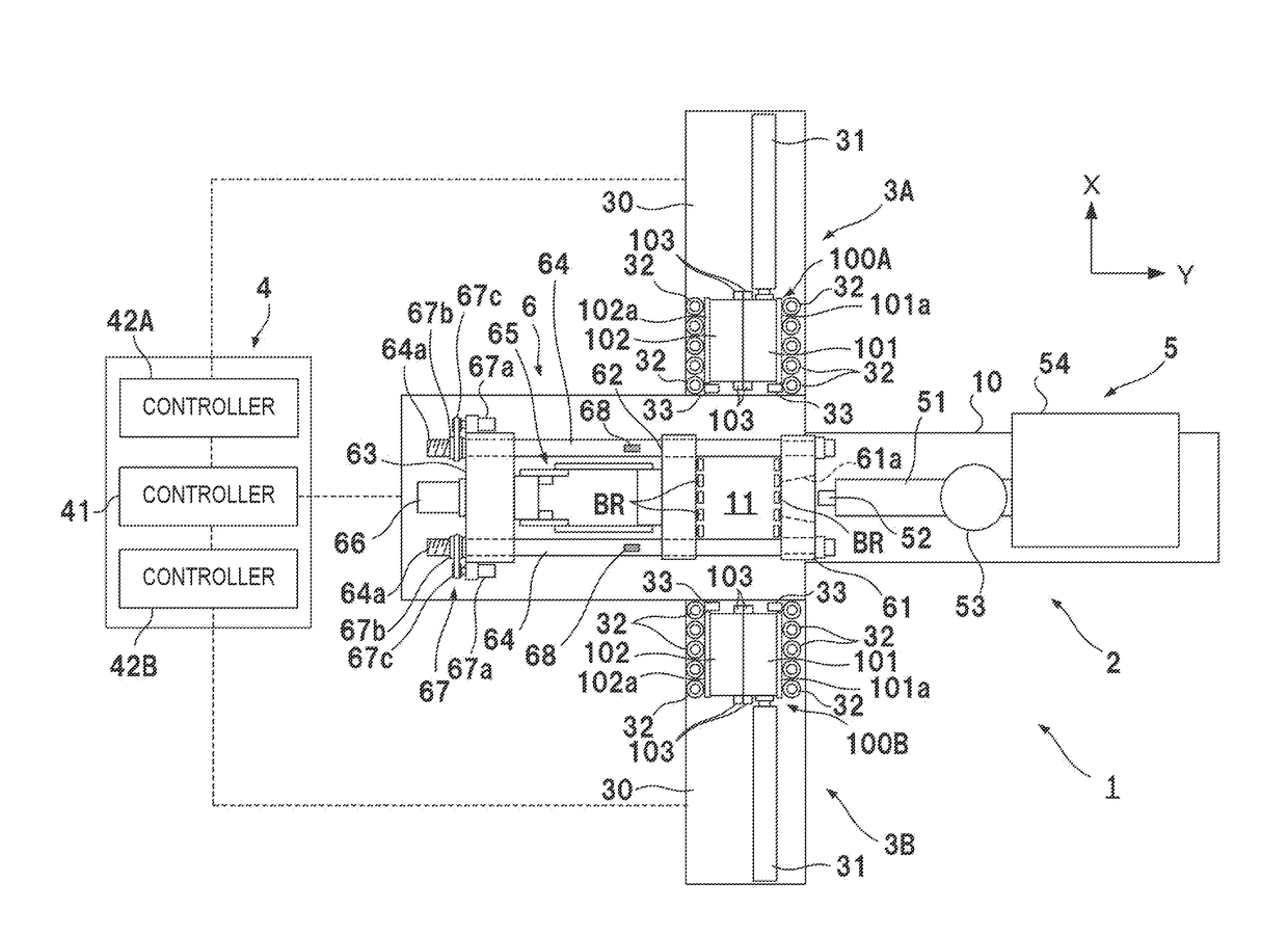
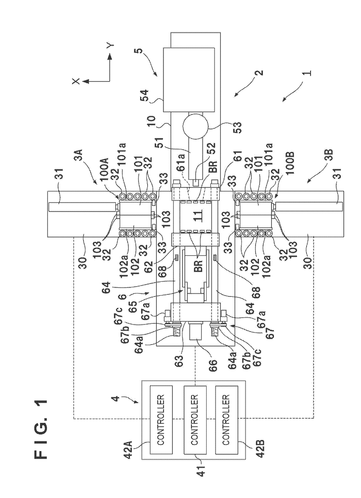
[0025]FIG. 1 is a plan view of an injection molding system 1 according to an embodiment of the present invention. The injection molding system 1 is a system including a horizontal type injection molding machine 2, conveying machines 3A and 3B, and a control apparatus 4, and that is for manufacturing a molded part while alternating a plurality of molds by the conveying machines 3A and 3B for the one injection molding machine 2. In the embodiment, two molds 100A and 100B are used. There are cases where the molds 100A and 100B are referred to collectively as the molds 100.

[0026]The molds 100 are a pair of a fixed mold 101 and a movable mold 102 which is opened / closed ...

second embodiment

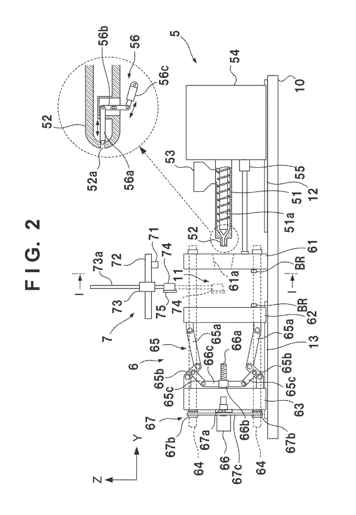
[0087]The mold 100A and the mold 100B may be molds for molding the same molded part, or may be molds for molding different molded parts. Irrespective of whether or not the molded parts to be molded are the same, there are cases in which between the mold 100A and the mold 100B the thickness and clamping force in the Y direction differs, but in the embodiment, it is possible to change the position at which to fix the movable platen 63 in relation to the tie-bars 64 by the adjusting mechanisms 67, and a setting change (step S10 of FIG. 5) is performed after alternating the molds (step S9 of FIG. 5), and therefore it is possible to set clamping to correspond to each mold.

[0088]If the mold 100A and the mold 100B are molds for molding different molded parts, there are cases in which it is necessary to replace the chuck plate 75 with something that corresponds to the type of the molded part. However, when the chuck plate 75 is replaced, time is required regardless of whether it is done man...

third embodiment

[0093]In the first embodiment, an example in which two molds 100A and 100B are alternated is explained, but three or more molds may be alternated. For example, a case in which three molds 100A-100C are alternated is explained. The mold 100A is loaded into the injection molding machine 2, and molded part ejection, clamping, and injection / dwelling is performed. The mold 100A is unloaded, the mold 100B is loaded into the injection molding machine 2, and molded part ejection, clamping, and injection / dwelling is performed. The mold 100B is unloaded, the mold 100C is loaded into the injection molding machine 2, and molded part ejection, clamping, and injection / dwelling is performed. The mold 100C is unloaded, the mold 100A is loaded into the injection molding machine 2, and molded part ejection, clamping, and injection / dwelling is performed. Thereafter, the same procedure is repeated. It is possible to employ as a conveyance apparatus of the three molds 100A-100C an apparatus that lines t...


PUM

PropertyMeasurementUnit
degree of freedomaaaaaaaaaa
thicknessaaaaaaaaaa
magnetic forceaaaaaaaaaa

Abstract

A method including a first step of performing clamping of a mold, injection and dwelling in an injection molding machine, a second step of performing a conveyance and a cooling of the mold outside of the machine, and a third step of performing a conveyance of the mold into the machine, an opening of the mold and an ejection of a molded part in the machine. The second step is performed for a first mold, the third step and the next first step are performed for a second mold. The first mold is conveyed by a first conveyance apparatus which is arranged on one lateral side of the machine. The second mold is conveyed by a second conveyance apparatus which is arranged on the other lateral side and is independently driven from the first conveyance apparatus.

Description

BACKGROUND OF THE INVENTIONField of the Invention[0001]The present invention relates to injection molding.Description of the Related Art[0002]In manufacturing of molded parts by an injection molding machine, an injection process of filling a resin into a mold after clamping, a dwelling process of pressing the resin into the mold at a high pressure in order to compensate for a volume decrease due to solidification of the resin, a cooling process of keeping the molded part in the mold until the resin is solidified, and an ejecting process of ejecting the molded part from the mold are performed repeatedly.[0003]In this type of molding method, a method that uses two molds with one injection molding machine in order to enhance productivity is proposed. For example, Japanese patent publication No. H7-119012 discloses a system in which molded part ejecting apparatuses are arranged on both sides of an injection molding machine. In this system, in the injection molding machine, an injection ...

Claims


Application Information

Patent Timeline
Patent Type & Authority Applications(United States)
IPC IPC(8): B29C45/33B29C45/73B29C45/78B29C45/80B29C45/04B29C45/42B29C45/76B29K105/00
CPCB29C45/332B29C45/04B29C45/42B29C45/73B29C45/80B29C45/78B29K2105/0067B29C2945/76568B29C2945/76531B29C2945/76013B29C2945/76224B29C2945/76732B29C45/7653B29C45/4225B29C45/0408B29C45/1742B29C45/661B29C45/72
Inventor NAKAMURA, TAKASHI
Owner CANON KK
Why Eureka
Try Eureka