Projection system and method for adjusting projection system

Active Publication Date: 2018-01-11
SEIKO EPSON CORP
View PDF6 Cites 6 Cited by
  • Summary
  • Abstract
  • Description
  • Claims
  • Application Information

AI Technical Summary

Benefits of technology

The invention allows multiple projectors to create a combined image that looks like a tiled image with less unevenness where the images overlap.

Problems solved by technology

In a system of this type, part of an image projected by each of the projectors is caused to overlap with an image projected by an adjacent projector, and adjustment is so made that unevenness of luminance and color is unnoticeable in the overlapping area where the projection images overlap with each other (see JP-A-2013-25076, for example).

Method used


Image

  • Projection system and method for adjusting projection system
  • Projection system and method for adjusting projection system
  • Projection system and method for adjusting projection system

Examples


first embodiment

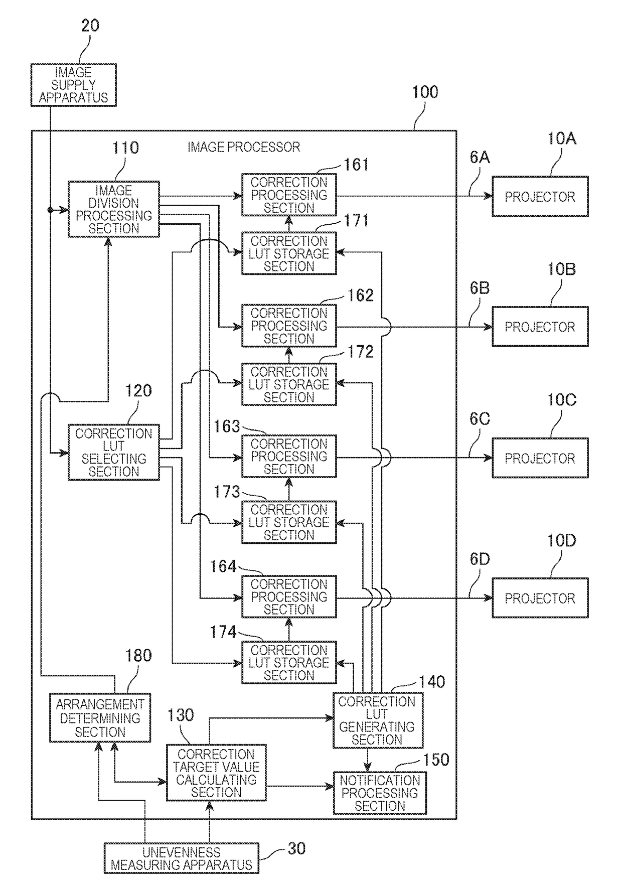
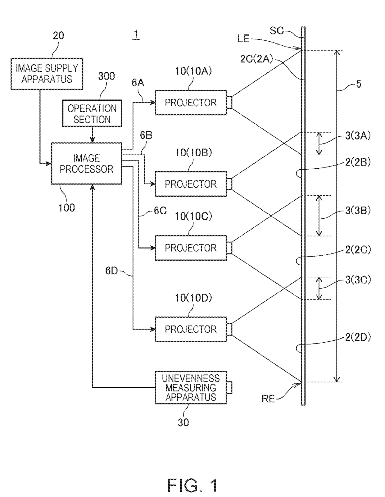
[0045]FIG. 1 is a block diagram showing the configuration of a projection system 1 according to a first embodiment to which the invention is applied.

[0046]The projection system 1 includes a plurality of projectors 10, which form a multi-projection system. The number of projectors 10 is preferably three or greater, more preferably, four or greater. The present embodiment will be described with reference to a case where four projectors 10A, 10B, 10C, and 10D are provided by way of example.

[0047]The four projectors 10A, 10B, 10C, and 10D project projection images 2A, 2B, 2C, and 2D, respectively, on a screen SC (projection surface). The projection images 2A, 2B, 2C, and 2D form a tiled image 5, which is a large image as a whole, on the screen SC. In FIG. 1, the screen SC is shown in a plan view, in which the upper side in FIG. 1 corresponds to a left end LE of the screen SC and the lower side in FIG. 1 corresponds to a right end RE of the screen SC. Each of the four projection images 2...

second embodiment

[0161]FIG. 14 is a functional block diagram showing, as a second embodiment to which the invention is applied, the configuration in which the image processor 100 and the projector 10A in the projection system 1 are replaced with a projector 10F.

[0162]The projector 1OF includes a control section 11A, a projection section 12A, and an image processing section 17A as the configuration corresponding to the control section 11, the projection section 12, and the image processing section 17 provided in the projector 10A. The functions of the control section 11A, the projection section 12A, and the image processing section 17A are the same as those of the control section 11, the projection section 12, and the image processing section 17.

[0163]The projector 10F further includes the image division processing section 110, the correction LUT selecting section 120, the correction target value calculating section 130, the correction LUT table generating section 140, the notification processing sec...


PUM


Abstract

A projection system includes three or more projectors. Each of the projectors includes a projection section that projects image light to form a projection image on a screen. The projectors are so arranged that the three or more projection images projected by the projectors form a tiled image. The projection image projected by any of the projectors and the projection image projected by an adjacent projector form an overlapping area where the projection images overlap with each other, and one of the overlapping areas differs from the other overlapping areas in terms of size.

Description

CROSS-REFERENCE[0001]The entire disclosure of Japanese Patent Application No. 2016-133079, filed Jul. 5, 2016 is expressly incorporated by reference herein.BACKGROUND1. Technical Field[0002]The present invention relates to a projection system and a method for adjusting the projection system.2. Related Art[0003]There is a known system of related art in which a plurality of projectors are arranged and project a tiled image. In a system of this type, part of an image projected by each of the projectors is caused to overlap with an image projected by an adjacent projector, and adjustment is so made that unevenness of luminance and color is unnoticeable in the overlapping area where the projection images overlap with each other (see JP-A-2013-25076, for example). In the configuration described in JP-A-2013-25076, an unevenness correction LUT (lookup table) is used to adjust the luminance of the projection images in the overlapping area. In more detail, also in consideration of the differ...

Claims


Application Information

Patent Timeline
IPC IPC(8): H04N9/31
CPCH04N9/3185H04N9/3194H04N9/3147H04N9/3182G03B21/147G03B21/13H04N9/3179
Inventor MIZUSHIRO, KENJI
Owner SEIKO EPSON CORP
Why Eureka
Try Eureka