Milling insert and a milling tool

a technology of milling insert and milling tool, which is applied in the direction of manufacturing tools, tool workpiece connection, transportation and packaging, etc., can solve the problems of irregular wear of the cutting edge, inability to adapt the cutting edge and clearance surface geometry inability to optimize the cutting precision etc., to achieve easy analysis, optimize the production of the milling insert as well as the machining of the insert seat in the tool body, and improve the effect of th

Active Publication Date: 2018-01-18
SANDVIK INTELLECTUAL PROPERTY AB
View PDF18 Cites 17 Cited by
  • Summary
  • Abstract
  • Description
  • Claims
  • Application Information

AI Technical Summary

Benefits of technology

[0005]A primary object of the present invention is to provide a milling insert and a milling tool suitable for ramping and for shoulder milling of small details, which milling insert and milling tool have properties optimized with regard to cutting precision, attachment precision and stability of the milling insert in the tool body of the milling tool, and wherein the production of the milling insert as well as the machining of the insert seat in the tool body is facilitated with respect to known milling inserts and milling tools. Another object is to provide a milling insert which may be adapted to achieve an optimised primary clearance behind the cutting edge without compromising the stability of the milling insert in the milling tool. Yet another object is to provide a milling insert on which flank wear can be more easily analysed and on which such wear of the cutting edge does not affect the support surfaces of the milling insert.

Problems solved by technology

However, this milling insert is not optimized with regard to ease of production.
Moreover, the geometry of the milling insert does not enable adaptation of the cutting edge and the clearance surfaces to different milling conditions.
Typically, the primary clearance behind the major cutting edge portion will vary along the major cutting edge portion, thus leading to irregular wear of the cutting edge and a strength of the cutting edge which varies along the major cutting edge portion.

Method used


Image

  • Milling insert and a milling tool
  • Milling insert and a milling tool
  • Milling insert and a milling tool

Examples


Embodiment Construction

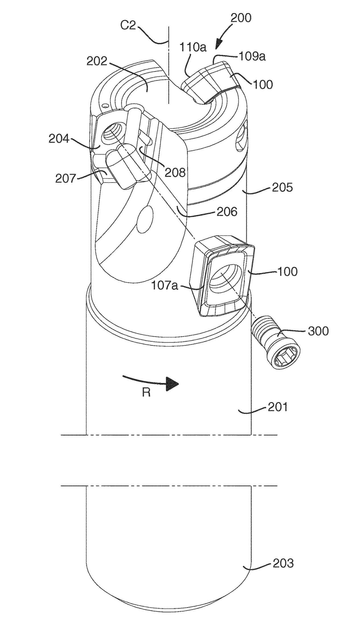
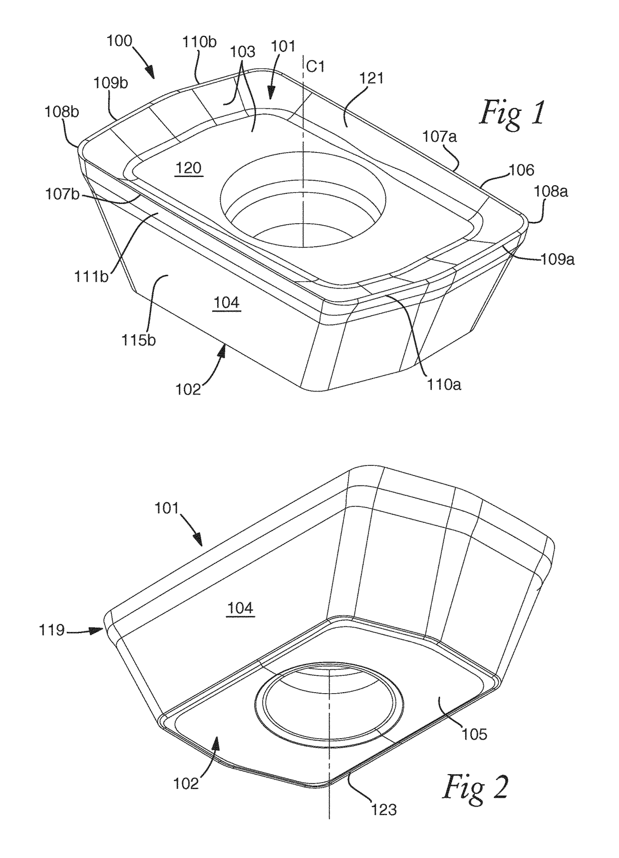
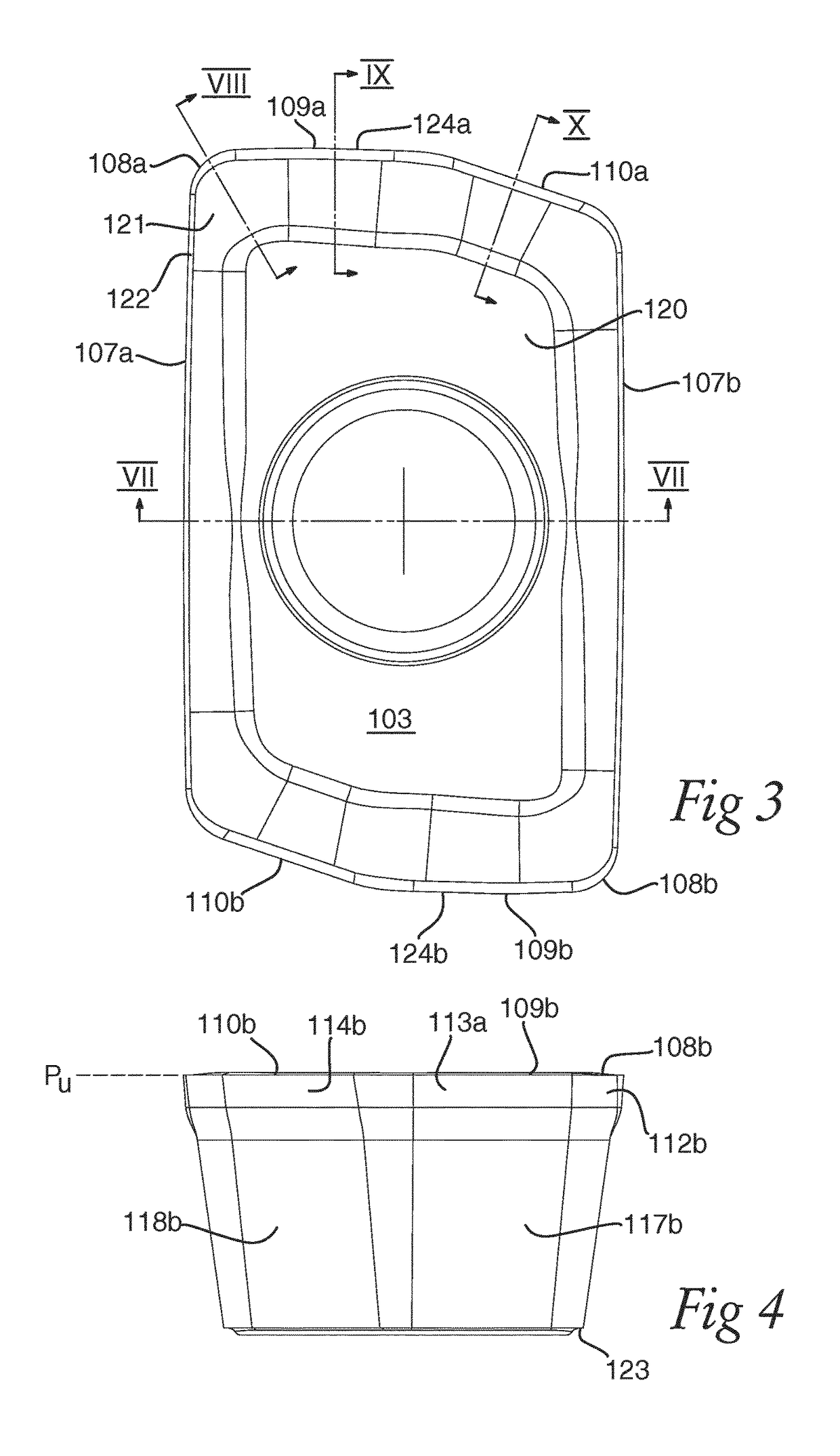
[0037]FIG. 1-10 show different views of a milling insert 100 intended for shoulder milling, i.e. milling at an entering angle of 90° according to an embodiment of the invention. The milling insert 100 is indexable with two index positions and has a positive basic shape. It comprises an upper side 101 and a lower side 102 opposite the upper side 101. A central axis C1 extends between the upper side 101 and the lower side 102. A central hole is provided for mounting the milling insert in a tool body. The upper side 101 comprises a rake surface 103 having a planar central region 120 extending around the central hole. The lower side 102 comprises a planar bottom surface 105. Around the periphery of the milling insert, a side surface 104 extends. A cutting edge 106 is formed between the rake surface 103 and the side surface 104. An upper extension plane PU is defined, extending in parallel with the bottom surface 105 at the level of the cutting edge 106. The cutting edge 106 extends in p...


PUM

PropertyMeasurementUnit
βaaaaaaaaaa
thicknessaaaaaaaaaa
thicknessaaaaaaaaaa

Abstract

A milling insert for shoulder milling having s a positive basic shape and includes an upper side having a rake surface, a lower side including a planar bottom surface, a side surface extending around the periphery of the milling insert, and a cutting edge formed between the side surface and the rake surface. The cutting edge has at least a major cutting edge portion, a corner radius cutting edge portion, a ramping cutting edge portion, and a surface wiping cutting edge portion. The side surface includes an upper set of primary clearance surfaces and a lower set of secondary clearance surfaces having a plurality of planar secondary clearance surfaces, wherein the upper set of primary clearance surfaces forms an overhang protruding with respect to the secondary clearance surfaces and extending around the entire upper periphery of the milling insert.

Description

TECHNICAL FIELD OF THE INVENTION[0001]The present invention relates to a milling insert intended for shoulder milling according to the preamble of claim 1. The invention also relates to a milling tool according to claim 16.BACKGROUND OF THE INVENTION AND PRIOR ART[0002]Milling tools for shoulder milling, such as shank-end milling tools, may advantageously be used for machining of shoulders, grooves and edges. For the machining of pockets and the like, it is preferable to use a milling tool having a ramping cutting edge portion, i.e. a cutting edge portion that is closer to a central axis of the milling tool than a major cutting edge portion used in the machining, and which is formed at an angle with respect to a surface wiping cutting edge portion. For cost-efficiency, it is preferable to use a milling tool which comprises on one hand a tool body, and on the other hand detachable and replaceable milling inserts.[0003]US2006 / 0013661 discloses a milling insert and a milling tool inten...

Claims


Application Information

Patent Timeline
Patent Type & Authority Applications(United States)
IPC IPC(8): B23C5/20B23C5/10
CPCB23C5/207B23C5/109B23C2200/0472B23C2240/24B23C2200/243B23C5/205B23C2200/08B23C2200/286B23C2200/126B23C2200/203B23C2200/0494B23C2210/045B23C5/202B23C2200/287B23C5/10B23C5/22
Inventor ROMAN, STEFAN
Owner SANDVIK INTELLECTUAL PROPERTY AB
Why Eureka
Try Eureka