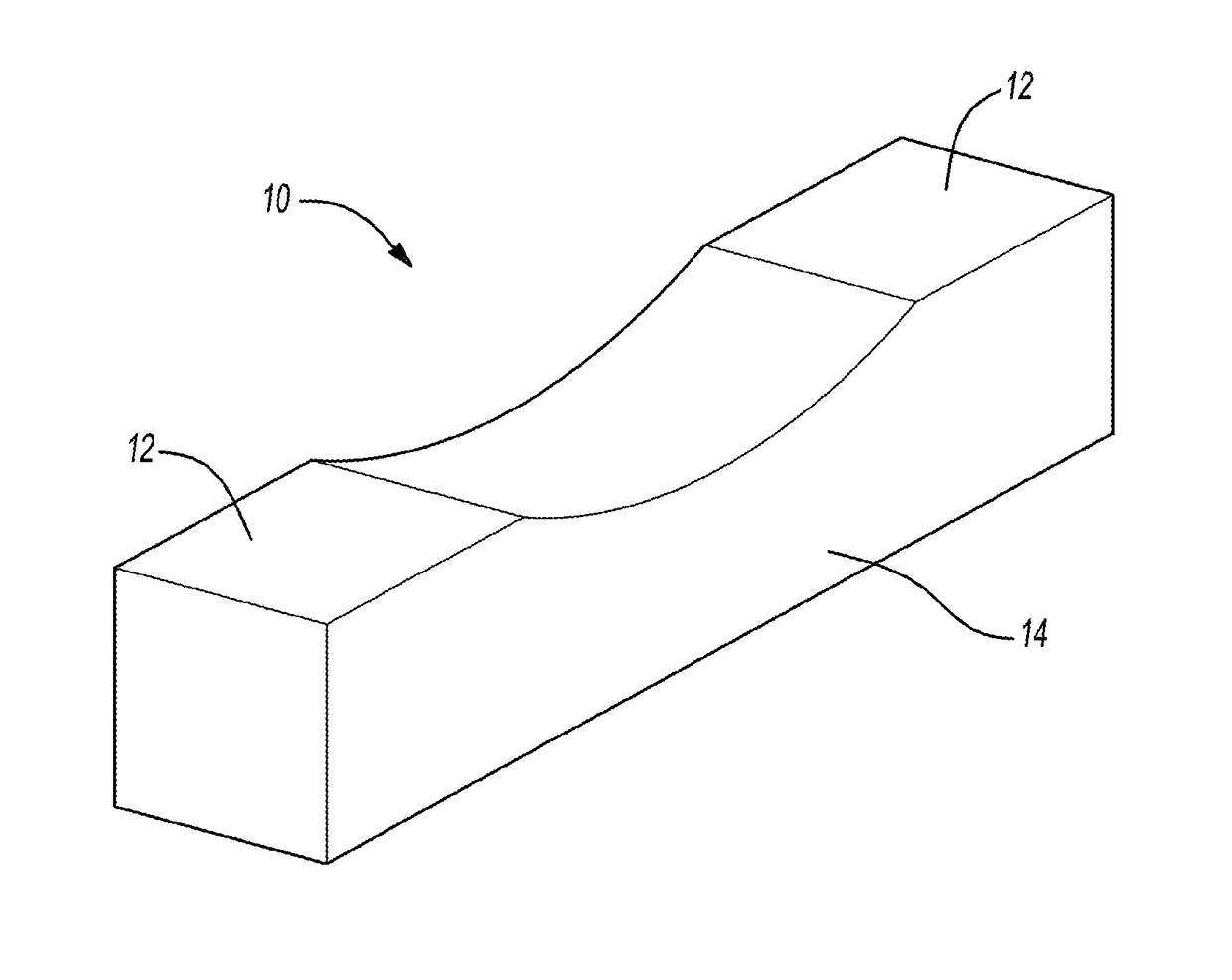
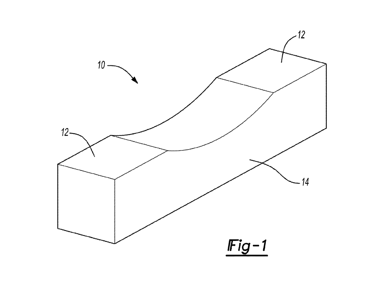
Durable railway tie

Active Publication Date: 2018-01-18
THE RGT OF THE UNIV OF MICHIGAN
View PDF8 Cites 1 Cited by
  • Summary
  • Abstract
  • Description
  • Claims
  • Application Information

AI Technical Summary

Benefits of technology

The patent text is discussing the problem of failure mechanisms in concrete railroad ties, which can lead to cracks and corrosion. These failures require frequent repairs and replacement, using up resources and energy. The invention of a self-healing ECC railroad tie is being developed to address this problem. The process involves tailoring the ECC to the specific needs of the railroad industry, using lightweight fillers to achieve optimal density and stiffness. The use of recycled tire rubber also contributes to the stiffness of the ECC. Overall, this invention aims to create a more durable, resilient, and sustainable railroad operation and service.

Problems solved by technology

Impaired railroad tie durability has been observed over the last decade, which has led to repeated replacement and undesired downtime of the rail line.
The lack of railroad tie durability has been linked to two primary mechanisms—Alkali-Silica Reaction (ASR) and brittle spalling of concrete, which can lead to corrosion of the pre-stressed steel components that are within the rail line as well as low abrasion resistance under the steel rail.
While the deterioration and lack of durability of railroad ties has sparked concern and interest from major railroad companies, no solution has been found and it remains a global rail industry problem.
One current disadvantage of concrete ties over timber ties is the excessively high stiffness, particularly when the ties are reinforced or prestressed with steel.
If prestressing can be eliminated, this may reduce the overall cost of railroad ties since prestressing is a relatively expensive process and the price of steel is continuously rising.
Removing prestressing steel further reduces the tie stiffness.
As well, railroad tie deterioration associated with corrosion of prestressing steel cannot take place when it is not present.
This type of materials development is important in order to ensure optimal infrastructure performance; however, it is not yet widely implemented in the field of civil engineering.

Method used


Image

  • Durable railway tie
  • Durable railway tie

Examples


Embodiment Construction

[0016]Example embodiments will now be described more fully with reference to the accompanying drawings.

[0017]Example embodiments are provided so that this disclosure will be thorough, and will fully convey the scope to those who are skilled in the art. Numerous specific details are set forth such as examples of specific components, devices, and methods, to provide a thorough understanding of embodiments of the present disclosure. It will be apparent to those skilled in the art that specific details need not be employed, that example embodiments may be embodied in many different forms and that neither should be construed to limit the scope of the disclosure. In some example embodiments, well-known processes, well-known device structures, and well-known technologies are not described in detail.

[0018]The terminology used herein is for the purpose of describing particular example embodiments only and is not intended to be limiting. As used herein, the singular forms “a,”“an,” and “the” ...


PUM

PropertyMeasurementUnit
Fractionaaaaaaaaaa
Lengthaaaaaaaaaa
Densityaaaaaaaaaa

Abstract

A railway tie being constructed of an engineered cementitious composite (ECC) material having: (1) a minimum of 2% tensile ductility of ECC, (2) complete absence of alkali-silica reaction (ASR), (3) high fatigue resistance of ECC at least five times that of normal concrete, (4) self-healing ability of ECC requiring only water and air, and (5) customization of ECC for lower stiffness in the tie (60% that of normal concrete) and higher abrasion resistance in the seat (three times that of normal concrete).

Description

CROSS-REFERENCE TO RELATED APPLICATIONS[0001]This application claims the benefit of U.S. Provisional Application No. 62 / 114,712, filed on Feb. 11, 2015. The entire disclosure of the above application is incorporated herein by reference.FIELD[0002]The present disclosure relates to railway ties and, more particularly, relates to railway ties being made of self-healing engineered cementitious composites.BACKGROUND AND SUMMARY[0003]This section provides background information related to the present disclosure which is not necessarily prior art. This section also provides a general summary of the disclosure, and is not a comprehensive disclosure of its full scope or all of its features.[0004]Railroad ties are an integral part of railroad track infrastructure. They are typically embedded in rock ballast roadbeds and the rails sit on top of the ties. The spacing between ties is about 0.5 m, so there can be as many as 2000 ties per kilometer of track. Historically, railroad ties are made of...

Claims


Application Information

Patent Timeline
IPC IPC(8): E01B3/32C04B16/06C04B14/06C04B28/04C04B18/14C04B103/32C04B103/44
CPCE01B3/32C04B28/04C04B18/146C04B14/06C04B16/06C04B2103/32C04B2103/44C04B2201/52C04B28/00E01B3/28C04B18/08C04B18/085C04B18/20C04B40/0675Y02A30/30Y02W30/91C04B16/0616C04B18/082C04B18/22
Inventor LI, VICTOR C.HERBERT, EMILY
Owner THE RGT OF THE UNIV OF MICHIGAN
Why Eureka
Try Eureka