Lighting apparatus

a technology of lighting apparatus and lighting device, which is applied in the direction of lighting and heating apparatus, light source combination, semiconductor devices for light sources, etc., can solve the problems of difficult to reproduce a blue sky by the lighting apparatus, and difficult to reproduce a sky that is recognized as the sky in nature, and achieves the effect of simple configuration

Active Publication Date: 2018-01-18
PANASONIC INTELLECTUAL PROPERTY MANAGEMENT CO LTD
View PDF6 Cites 7 Cited by
  • Summary
  • Abstract
  • Description
  • Claims
  • Application Information

AI Technical Summary

Benefits of technology

[0008]According to the present disclosure, it is possible to reproduce an artificial sky with a simple configuration.

Problems solved by technology

However, when the lighting apparatus is installed on a wall, a ceiling, or the like in facilities, it is difficult to reproduce a blue sky by the lighting apparatus, because a color temperature or a luminance level is uniform.
However, with a video display device such as a display, a position of the surface of a light emitter is easily and precisely recognized physically, due to granularity of image elements or the like, and thus it is difficult to reproduce a sky that is recognizes as the sky in nature.

Method used


Image

  • Lighting apparatus
  • Lighting apparatus
  • Lighting apparatus

Examples


embodiment 1

[0027]The following describes a lighting apparatus according to Embodiment 1 of the present disclosure.

[0028](Configuration)

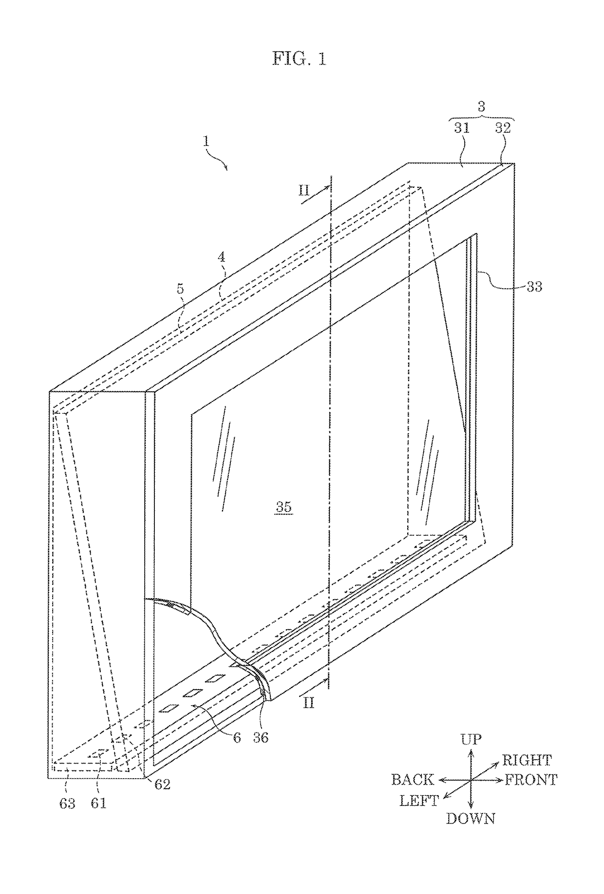
[0029]First, a configuration of lighting apparatus 1 according to the present embodiment shall be described with reference to FIG. 1.

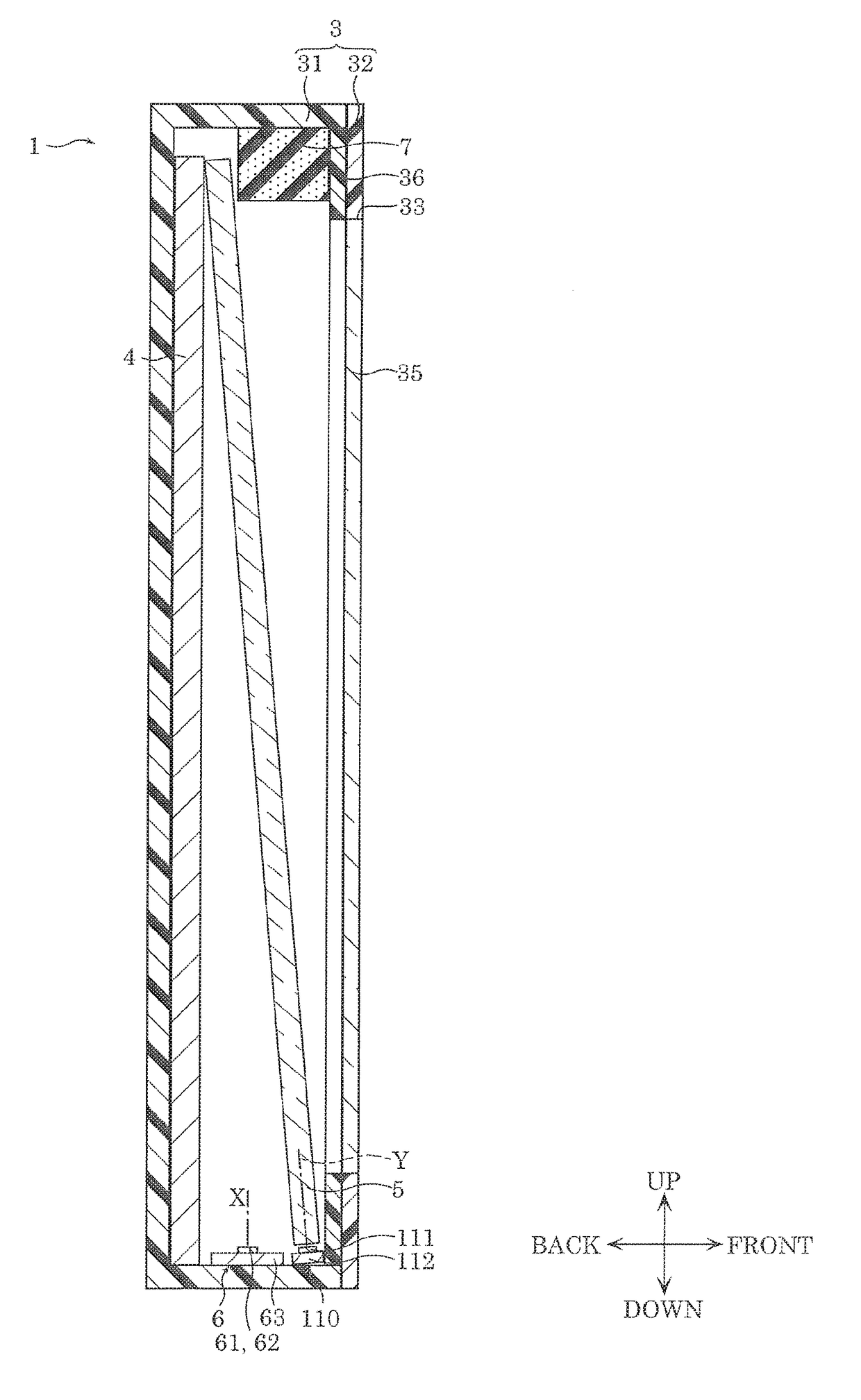
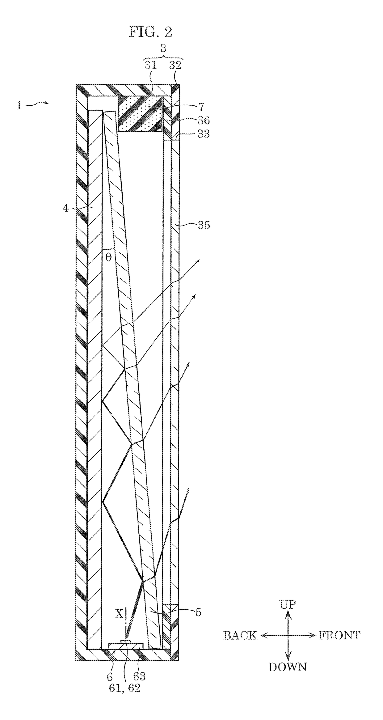
[0030]FIG. 1 is a perspective view which illustrates lighting apparatus 1 according to Embodiment 1. FIG. 2 is a cross-sectional view which illustrates lighting apparatus 1 along the line II-II of FIG. 1, according to Embodiment 1. FIG. 3 is a block diagram which illustrates lighting apparatus 1 according to Embodiment 1.

[0031]In FIG. 1, the directions of front, back, left, right, up, and down are shown, where the direction from the center of lighting apparatus 1 toward light-transmissive plate 35 is defined as a front direction, and the direction from the center of lighting apparatus 1 toward first light emitting module 6 is defined as a down direction. It should be noted that the directions illustrated in FIG. 2 and subsequent f...

embodiment 2

[0100](Configuration)

[0101]The following describes a configuration of lighting apparatus 100 according to Embodiment 2, with reference to FIG. 5 and FIG. 6.

[0102]FIG. 5 is a cross-sectional view which illustrates lighting apparatus 100 along the line II-II of FIG. 1, according to Embodiment 2. FIG. 6 is a block diagram which illustrates lighting apparatus 100 according to Embodiment 2.

[0103]Embodiment 2 is different from Embodiment 1 in that orange light source 111 and power source 120 are included in addition to the configuration according to Embodiment 1. Furthermore, lighting apparatus 100 according to Embodiment 2 is similar to lighting apparatus 100 according to Embodiment 1, the same structural components are assigned with the same reference signs, and detailed descriptions for the structural components will be omitted.

[0104]As illustrated in FIG. 5 and FIG. 6, lighting apparatus 100 further includes second light emitting module 110.

[0105]Second light emitting module 100 is a ...


PUM


Abstract

A lighting apparatus includes: a light source; a reflector plate which reflects light; and a diffuser plate which is light transmissive and is disposed to face the reflector plate. A gap between the diffuser plate and the reflector plate gradually decreases from a lower portion side of the diffuser plate and the reflector plate to an upper potion side of the diffuser plate and the reflector plate. The light source is disposed on the lower portion side to emit light toward the diffuser plate and the reflector plate.

Description

CROSS REFERENCE TO RELATED APPLICATION[0001]This application claims the benefit of priority of Japanese Patent Application Number 2016-137649 filed on Jul. 12, 2016, the entire content of which is hereby incorporated by reference.BACKGROUND1. Technical Field[0002]The present disclosure relates to a lighting apparatus capable of emitting light imitating the sky in nature, and performing illumination rendering for providing a sense of infinite depth as if viewing the distant sky.2. Description of the Related Art[0003]Conventionally, a planar lighting apparatus which includes a light source for emitting white light, a reflection sheet for reflecting light, and a light guide plate has been disclosed (see, for example, Japanese Unexamined Patent Application Publication No. 2016-12540).[0004]The planar lighting apparatus is capable of suppressing color unevenness occurring on the light guide plate and uniforming color tones of emission light.SUMMARY[0005]However, when the lighting apparat...

Claims


Application Information

Patent Timeline
Patent Type & Authority Applications(United States)
IPC IPC(8): F21V13/10H05B33/08F21S10/00F21V11/00F21V7/05F21V3/02H05B37/02F21V19/00H05B44/00
CPCF21V13/10F21V7/05F21S10/00F21V11/00F21Y2115/10H05B37/0272F21V19/0015H05B33/0845F21V3/02F21V7/0016F21V7/0033F21Y2105/00F21Y2103/10F21Y2113/13H05B45/20H05B47/19
Inventor TAKESHITA, HIRONORI
Owner PANASONIC INTELLECTUAL PROPERTY MANAGEMENT CO LTD
Why Eureka
Try Eureka