Tracking control device, tracking control method, tracking control program, and automatic tracking imaging system

a tracking control and control method technology, applied in the direction of direction/deviation determining electromagnetic systems, instruments, television systems, etc., can solve the problems of irregular control delay, inability to cope, irregular control delay, etc., and achieve high-quality moving image

Active Publication Date: 2018-01-18
FUJIFILM CORP
View PDF25 Cites 20 Cited by
  • Summary
  • Abstract
  • Description
  • Claims
  • Application Information

AI Technical Summary

Benefits of technology

[0012]According to this aspect, the position of the target is predicted in consideration of a control delay due to communication. Pan and / or tilt of the camera is controlled on the basis of the target prediction position. Accordingly, even in a case where the control delay is caused by communication, the camera can be caused to follow accurately. Further, according to this aspect, the dead zone is set, and the camera is set not to follow for a motion of the target that is predicted in the dead zone. Thus, it is possible to prevent the camera from moving little by little and to capture a high-quality moving image.
[0055]According to the present invention, following performance is high, and it is possible to capture a high-quality moving image.

Problems solved by technology

However, in such a system that remotely controls the camera, there is a problem in that an irregular control delay occurs according to a state of communication between the camera and the control terminal.
In JP2007-295175A, a motion of the target is predicted and the pan and tilt of the camera are controlled, but there is a drawback in that it is not possible to cope with a case where the irregular control delay occurs since the prediction is performed after a certain time.
Such irregular control delay also occurs when the control terminal is executing a plurality of processes in parallel.
That is, when the camera is remotely controlled by a computer that executes a plurality of processes in parallel using one central processing unit (CPU), the irregular control delay occurs according to a use state of the CPU.
Further, there is a problem in that frequent small shaking easily occurs if the motion of the target is predicted and the pan and / or tilt of the camera is controlled.
That is, there is a problem in that an error occurs due to prediction and frequent small shaking occurs easily in order to correct this error.
Therefore, it is not possible to effectively prevent low-frequency motion with a small motion.

Method used


Image

  • Tracking control device, tracking control method, tracking control program, and automatic tracking imaging system
  • Tracking control device, tracking control method, tracking control program, and automatic tracking imaging system
  • Tracking control device, tracking control method, tracking control program, and automatic tracking imaging system

Examples


second embodiment

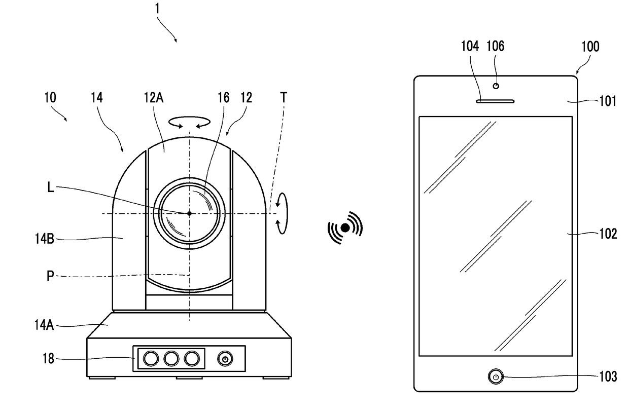
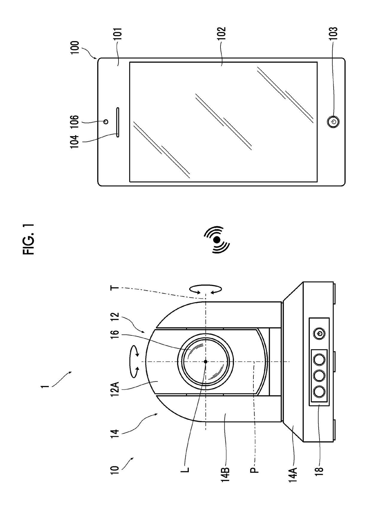
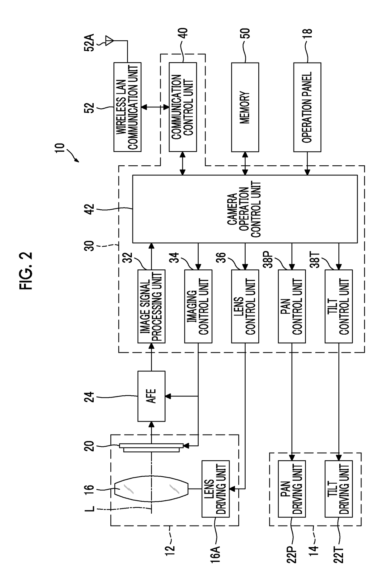
[0210]FIG. 13 is a block diagram illustrating a system configuration of the control terminal functioning as the tracking control device of the

[0211]The tracking control device of this embodiment includes a control amount determination unit 230 and a control amount correction unit 232. The tracking control device of this embodiment has the same configuration as the configuration of the tracking control device in the above embodiment except that control amount determination unit 230 and the control amount correction unit 232 are included. Therefore, the same components as those of the tracking control device in the above embodiment are denoted by the same reference signs, and description thereof will be omitted.

[0212]The control amount determination unit 230 compares a control amount calculated by the control amount calculation unit 222 with a threshold value and determines whether or not the calculated control amount is equal to or more than a threshold value.

[0213]The threshold valu...

third embodiment

[0229]FIG. 16 is a block diagram illustrating a system configuration of a control terminal functioning as the tracking control device of the

[0230]The tracking control device of this embodiment is different from the tracking control device of the second embodiment in that a dead zone changing unit 234 is included. Therefore, the dead zone changing unit 234 will be described herein, other configurations are denoted by the same reference signs as those of the tracking control device of the second embodiment, and description thereof will be omitted.

[0231]The dead zone changing unit 234 increases or decreases a range of the dead zone set by the dead zone setting unit 224 according to a state of the target. In this embodiment, the dead zone is increased or decreased according to the movement direction of the target to be predicted. Specifically, the dead zone in the movement direction of the target to be predicted is decreased.

[0232]The dead zone changing unit 234 acquires information on ...

fourth embodiment

[0268]FIG. 21 is a block diagram illustrating a system configuration of a control terminal functioning as the tracking control device of the

[0269]The tracking control device of this embodiment is different from the tracking control device of the second embodiment in that a predictiton reliability calculation unit 236 and a dead zone changing unit 234 are included. Therefore, only the prediction degree of reliability calculation unit 236 and the dead zone changing unit 234 will be described herein, other configurations are denoted by the same reference signs as those of the tracking control device of the second embodiment, and description thereof will be omitted.

[0270]The prediction degree of reliability calculation unit 236 calculates the degree of reliability of prediction, that is, a degree of reliability of the target prediction position predicted by the target position prediction unit 220 on the basis of the control delay time estimated by the control delay time estimation unit ...


PUM


Abstract

An automatic tracking imaging system that remotely controls a camera in a control terminal and images a target while automatically tracking the target, the control terminal includes a target position detection unit that detects a position of the target, a control delay time estimation unit that estimates a time T at which a control delay occurs, a target position prediction unit that predicts a position of the target after the time T, a control amount calculation unit that calculates a control amount of pan and / or tilt of the camera required to move a center of an imaging screen to a predicted position of target, a determination unit that determines whether or not the target prediction position belongs to a dead zone, and an instruction unit that instructs the camera to execute the pan and / or tilt, and the camera is instructed to execute pan and tilt from the instruction unit.

Description

CROSS-REFERENCE TO RELATED APPLICATIONS[0001]The present application is a Continuation of PCT International Application No. PCT / JP2015 / 081033 filed on Nov. 4, 2015 claiming priority under 35 U.S.C. §119(a) to Japanese Patent Application No. 2015-064772 filed on Mar. 26, 2015. Each of the above applications is hereby expressly incorporated by reference, in their entirety, into the present application.BACKGROUND OF THE INVENTION1. Field of the Invention[0002]The present invention relates to a tracking control device, a tracking control method, a tracking control program, and an automatic tracking imaging system for remotely controlling pan and / or tilt of a camera and imaging a target while tracking the target.2. Description of the Related Art[0003]An automatic tracking imaging system that images a moving subject while automatically tracking the subject using a camera having a pan and / or tilt function is known.[0004]Generally, in an automatic tracking imaging system, a position of a ta...

Claims


Application Information

Patent Timeline
Patent Type & Authority Applications(United States)
IPC IPC(8): G01S3/786H04N5/232H04N7/18G02B7/08
CPCG01S3/7864H04N5/23296H04N5/232H04N7/18G02B7/08H04N23/661H04N23/61H04N23/635H04N23/695H04N23/69
Inventor IRIE, FUMINORI
Owner FUJIFILM CORP
Why Eureka
Try Eureka