Spectrally Encoded Probe with Multiple Diffraction Orders

a probe and diffraction order technology, applied in the field of endoscopes, can solve the problems of system difficulty in manufacturing and assembly, color information loss or convoluted spatial information, and large size of the prob

Active Publication Date: 2018-01-18
THE GENERAL HOSPITAL CORP +1
View PDF0 Cites 15 Cited by
  • Summary
  • Abstract
  • Description
  • Claims
  • Application Information

AI Technical Summary

Benefits of technology

[0007]Accordingly, it can be beneficial to address and / or overcome at least some of the deficiencies indicated herein above, and thus to provide a new color SEE probe that can provide color viewing without the size, rotary junction, or fabrication demands of prior systems.

Problems solved by technology

However, since SEE images utilize wavelength information to encode spatial location therefore important color information is lost or convoluted with the spatial information.
However, this system is not easily manufactured and assembled and multiple fibers must be sent through a multiple channel rotary junction for use in in vivo imaging.
The multiple fibers increase the size of the probe which reduces the number of applicable uses and invasiveness of use.
Additionally, other solutions for color SEE which included multiple grating patterns on a small grating surface can be difficult and / or expensive to fabricate and combine into the SEE apparatus.

Method used


Image

  • Spectrally Encoded Probe with Multiple Diffraction Orders
  • Spectrally Encoded Probe with Multiple Diffraction Orders
  • Spectrally Encoded Probe with Multiple Diffraction Orders

Examples


first embodiment

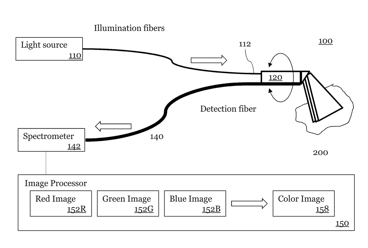
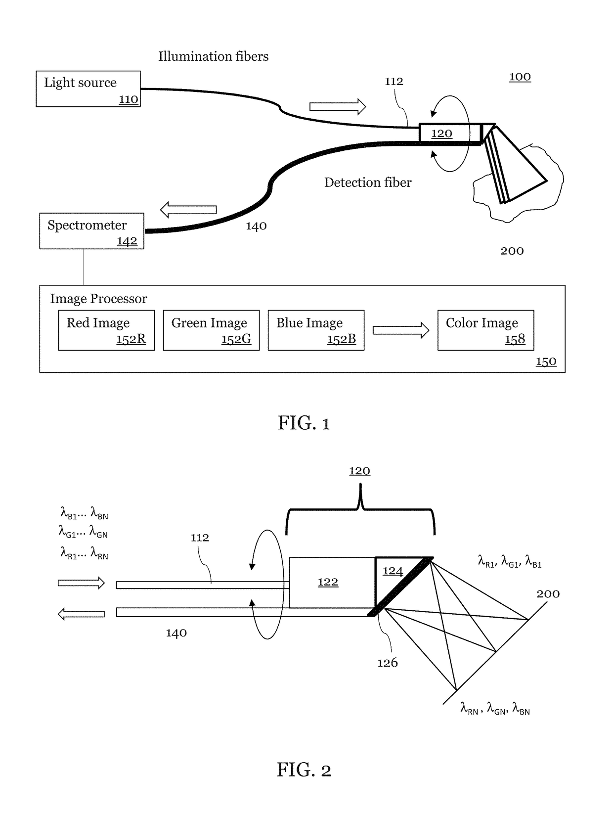
[0055]An exemplary embodiment of a SEE probe system 100 according to the present disclosure is shown in FIG. 1. This exemplary SEE probe system 100 may include a light source 110, a probe 120, a spectrometer 142, and an image processor 150. In this embodiment, broadband light from the light source 110 is coupled into a light guiding component which may be an illumination optical fiber 112.

[0056]The broadband light has sufficient bandwidth to allow for spatial resolution along the spectrally dispersed dimension. In some embodiments, the broadband light is a broadband visible light sources that includes a blue band of light (including wavelength λB1 to λBN), a green band of light (λG1 to λGN), and a red band of light (λR1 to λRN). For example, the blue band contains 400-500 nm light, the green band contains 5000-600 nm light, and the red band contains 600- 800 nm. In other embodiments, the wavelengths of the broadband light are optimized for identifying specific features such as blood...

second embodiment

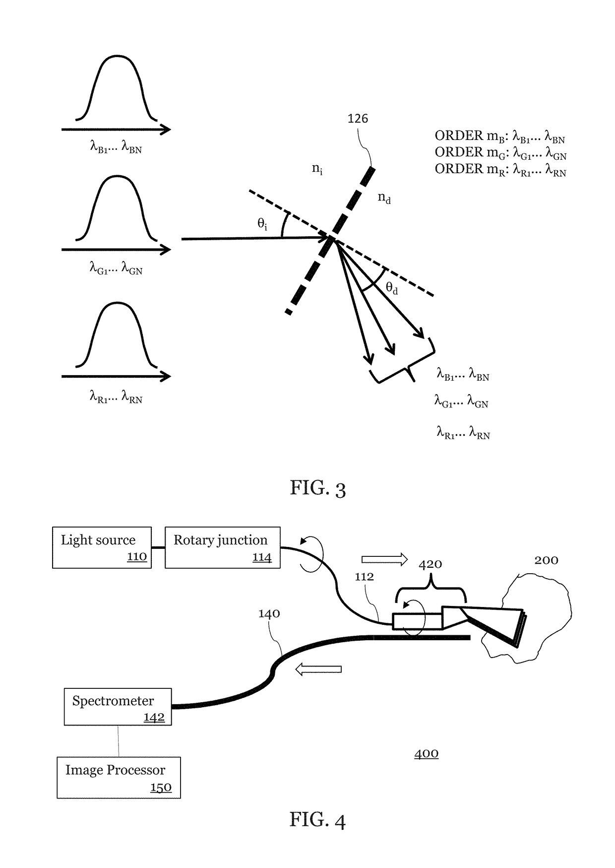
[0088]FIG. 4 is an illustration of a forward viewing SEE probe system 400 in which an embodiment may be implemented. The forward view SEE probe system also illustrates the use of a rotary junction 114 between the light source no and the probe 420.

[0089]As shown in FIG. 5, a light guiding component 112 (shown as an illumination fiber) transmits broadband light to the probe 120. A second light guiding component 140 (shown as a detection fiber) collects light. The probe 420 includes a light focusing component 122 and a grating component 126 which is shown attached to a spacer 524. The spacer has a mirror surface 528. The mirror 528 may be achieved, for example, by a reflective coating, a metal coating, or by using total internal reflection. The light guiding component 122 may be, for example, a GRIN lens or a ball lens and is fixed to an angle-polished spacer 524. The spacer 524 may be made of, but is not limited to, glass, heat-curable resin, UV-curable resin, or plastic.

[0090]As show...


PUM


Abstract

A spectrally encoded endoscopic probe. The probe has a light guiding component, a light focusing component, and a grating component. The probe is configured such that a set of light beams of multiple wavelengths are diffracted by the grating component in different orders at substantially the same angle. The set of light beams includes at least 3 light beams. Each light beam among the set of light beams is associated with a different wavelength.

Description

CROSS-REFERENCE TO RELATED APPLICATIONS[0001]This application claims the benefit of U.S. Provisional Application No. 62 / 363,119, filed Jul. 15, 2016. U.S. Provisional Application No. 62 / 363,119 is hereby incorporated by reference.BACKGROUNDField of Art[0002]The present disclosure relates to endoscopes. More particularly, the disclosure exemplifies spectrally encoded endoscopic probes.Description of the Related Art[0003]Medical probes have the ability to provide images from inside the patient's body. Considering the potential damage to a human body caused by the insertion of a foreign object, it is preferable for the probe to be as small as possible. Additionally, the ability to image within small pathways such as small vessels, small ducts, small needles, cracks etc., requires a small probe size.[0004]One useful medical probe employs spectrally encoded endoscopy (“SEE”) technology, which is a miniature endoscopy technology that can conduct high-definition imaging through a sub-mm di...

Claims


Application Information

Patent Timeline
Patent Type & Authority Applications(United States)
IPC IPC(8): G02B23/24A61B1/07A61B1/06G02B27/42H04N5/225
CPCG02B23/2407H04N5/2256G02B23/2469H04N2005/2255A61B1/0638A61B1/07G02B27/4227A61B1/00009A61B1/00096A61B1/00172G02B23/2423A61B1/0605H04N23/56H04N23/555
Inventor IKUTA, MITSUHIROKANG, DONGKYUNDO, DUKHOTEARNEY, GUILLERMO
Owner THE GENERAL HOSPITAL CORP
Why Eureka
Try Eureka