Endoscope and variable power optical system for the same

a technology of variable power and endoscope, which is applied in the field of variable power optical system of endoscope and endoscope, can solve the problems of difficult installation in the fine tip portion of the endoscope, the effect of reducing the degree of freedom regarding disposing of components, and the effective diameter of the most object side negative lens needs to be increased, so as to achieve the effect of enabling the use of electronic scopes

Active Publication Date: 2018-01-18
HOYA CORP
View PDF1 Cites 5 Cited by
  • Summary
  • Abstract
  • Description
  • Claims
  • Application Information

AI Technical Summary

Benefits of technology

[0048]When the focal length of the second lens group G2 is defined as f2 (unit: mm), the variable power optical system 100 for an endoscope is configured to satisfy the following condition (4):
[0049]By satisfying the condition (4), it becomes possible to secure the moving amount of the second lens group G2 required for the variable power while suppressing the entire length of the variable power optical system 100 for an endoscope.
[0050]When, regarding the condition (4), f2 / fw gets larger than equal to 5, the value of the right term, the power of the second lens group G2 becomes too small, and thereby the moving amount of the second lens group G2 required for the variable power becomes large and the entire length of the variable power optical system 100 for an endoscope becomes large. As a result, it becomes necessary to lengthen the entire length of the tip portion 12 of the electronic scope 1 being the rigid part in order to accommodate the variable power optical system 100 for an endoscope having the long entire length. Furthermore, when, regarding the condition (4), f2 / fw gets larger than equal to 5, the value of the right term, the observation magnification becomes too high, and thereby the operability of the electronic scope 1 when the observation is conducted at the telephoto end decreases. For example, in the observation, the tip portion 12 of the electronic scope 1 moves largely in response to a slight operation, and therefore it becomes difficult for the operator to bring an area which the operator wants to observe within the angle of view.
[0051]When, regarding the condition (4), f2 / fw gets smaller than equal to 2, the value of the left term, the power of the second lens group G2 becomes too strong, and therefore Petzval's sum becomes large in the negative direction and the curvature of filed occurs largely although the moving amount of the second lens group G2 required for the variable power can be suppressed.
[0052]When the focal length of the third lens group G3 is defined as f3 (unit: mm), the variable power optical system 100 for an endoscope is configured to satisfy the following condition (5):
[0053]By satisfying the condition (5), the exit angle of light proceeding from the variable power optical system 100 for an endoscope to the solid-state image pickup device can be suppressed over the region from the wide angle end to the telephoto end.

Problems solved by technology

However, a lens configuration of a negative-leading type (a type in which a most object side lens is a negative lens) exemplified in the patent document 1 has a drawback that the effective diameter of the most object side negative lens needs to be increased to suppress occurrence of aberrations while securing an angle of view at the wide angle end.
A variable power optical system of such a negative-leading type decreases a degree of freedom regarding disposing of components (e.g., a light guide, a forceps, an air supply or water supply channel) to be installed in a tip portion of an endoscope, and is hard to be installed in a fine tip portion of an endoscope.
Furthermore, since fluctuation of aberration becomes larger when the observing magnification is changed, it is difficult to keep the adequate optical performance over the entire region from the wide angle end to the telephoto end.

Method used


Image

  • Endoscope and variable power optical system for the same
  • Endoscope and variable power optical system for the same
  • Endoscope and variable power optical system for the same

Examples


example 1

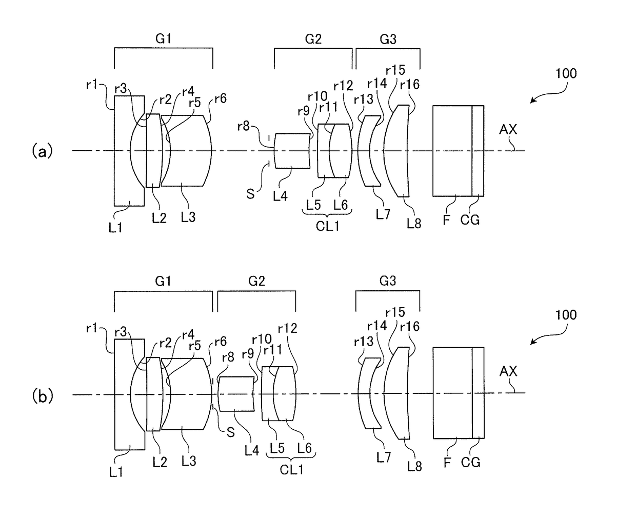
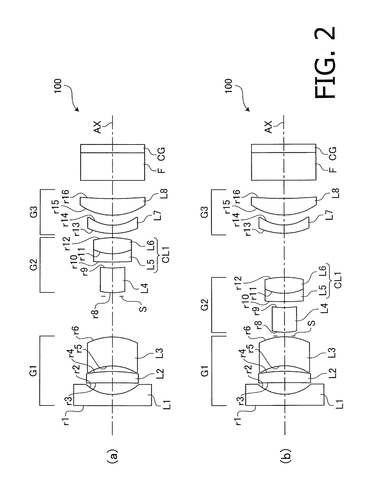
[0061]As described above, the variable power optical system 100 for an endoscope according to the example 1 has the configuration shown in FIG. 2.

[0062]Table 1 shows a concrete numerical configuration (design values) of the variable power optical system 100 for an endoscope (and the components disposed on the rear side thereof) according to the example 1. The surface number NO indicated in the top filed (surface data) in Table 1 corresponds to the surface reference rn (n: natural number) in FIG. 2, excepting the surface number 7 for the aperture stop S. In the top field of Table 1, R (unit: mm) denotes the radius of curvature of each surface of an optical component, D (unit: mm) denotes a thickness of an optical component or an interval between optical components on the optical axis, N(d) denotes a refractive index at d-line (wavelength of 588 nm), and νd denotes Abbe number at d-line.

[0063]The lower field (various data) of Table 1 shows, for each of the wide angle end and the telep...

example 2

[0066]Each of FIGS. 4(a) and 4(b) is a cross sectional view illustrating arrangement of optical components including the variable power optical system 100 for an endoscope according to the example 2. FIG. 4(a) illustrates the lens arrangement when the position of the variable power is at the wide angle end. FIG. 4(b) illustrates the lens arrangement when the position of the variable power is at the telephoto end.

[0067]Graphs A to D in FIG. 5(a) are aberration diagrams illustrating the various aberrations when the position of the variable power is at the wide angle end in the variable power optical system 100 for an endoscope according to the example 2. Graphs A to D in FIG. 5(b) are aberration diagrams illustrating the various aberrations when the position of the variable power is at the telephoto end in the variable power optical system 100 for an endoscope according to the example 2.

[0068]Table 2 shows a concrete numerical configuration and specifications of the optical components...

example 3

[0070]Each of FIGS. 6(a) and 6(b) is a cross sectional view illustrating arrangement of optical components including the variable power optical system 100 for an endoscope according to the example 3. FIG. 6(a) illustrates the lens arrangement when the position of the variable power is at the wide angle end. FIG. 6(b) illustrates the lens arrangement when the position of the variable power is at the telephoto end.

[0071]Graphs A to D in FIG. 7(a) are aberration diagrams illustrating the various aberrations when the position of the variable power is at the wide angle end in the variable power optical system 100 for an endoscope according to the example 3. Graphs A to D in FIG. 7(b) are aberration diagrams illustrating the various aberrations when the position of the variable power is at the telephoto end in the variable power optical system 100 for an endoscope according to the example 3.

[0072]Table 3 shows a concrete numerical configuration and specifications of the optical components...


PUM


Abstract

A variable power optical system for an endoscope comprising a first lens group having a negative power, a second lens group having a positive power and a third lens group, and wherein the first lens group includes at least a negative lens having a concave surface pointing to an image side and a positive meniscus lens having a concave surface pointing to an object side, the second lens group includes at least a meniscus lens having a convex surface pointing to the object side and a cemented lens formed by cementing together a negative lens and a positive lens, and the third lens group includes at least a positive lens having a convex surface pointing to the object side, and wherein the variable power optical system for an endoscope is configured to satisfy a predetermined condition.

Description

TECHNICAL FIELD[0001]The present invention relates a variable power optical system for an endoscope and an endoscope provided with such a variable power optical system.BACKGROUND ART[0002]In a medical field, an endoscope (a fiber scope or an electronic scope) is generally known as a device for observing a body cavity of a patient and has been practically used. Among endoscopes of this type, there is an endoscope provided with a variable power optical system having the variable power function for conducting fine observation for lesions.[0003]For example, Japanese Patent Publication No. JP4819969B (hereafter, referred to as a “patent document 1”) describes a concrete configuration of a variable power optical system for an endoscope. The variable power optical system for an endoscope described in the patent document 1 includes a first lens group having a negative power, a second lens group having a positive power and a third lens group having a positive power which are arranged in this...

Claims


Application Information

Patent Timeline
Patent Type & Authority Applications(United States)
IPC IPC(8): G02B23/24G02B15/177A61B1/00
CPCG02B23/2438A61B1/0019G02B15/177G02B15/14G02B15/16A61B1/00096A61B1/00186A61B1/00188A61B1/05A61B1/00163G02B15/143507G02B15/143503
Inventor NASU, SACHIKOFUJII, HIROAKI
Owner HOYA CORP
Why Eureka
Try Eureka