Vibration motor

a vibration motor and top plate technology, applied in mechanical vibration separation, dynamo-electric machines, magnetic circuit shapes/forms/construction, etc., can solve the problem of not being able to form a magnetic path between the two magnets without increasing so as to improve the responsiveness of the vibration motor, increase the magnetic force of the magnet, and increase the thickness of the top plate portion.

Active Publication Date: 2018-01-25
SANYO SEIMITSU
View PDF4 Cites 24 Cited by
  • Summary
  • Abstract
  • Description
  • Claims
  • Application Information

AI Technical Summary

Benefits of technology

[0009]With the vibration motor according the exemplary embodiment of the present application, it is possible to form a magnetic path without increasing the thickness of the top plate portion and to

Problems solved by technology

However, in the vibration motor described in CN 202435225 U, even if the magnetic force is increased by using large magnets,

Method used


Image

  • Vibration motor
  • Vibration motor
  • Vibration motor

Examples


first embodiment

1. First Embodiment

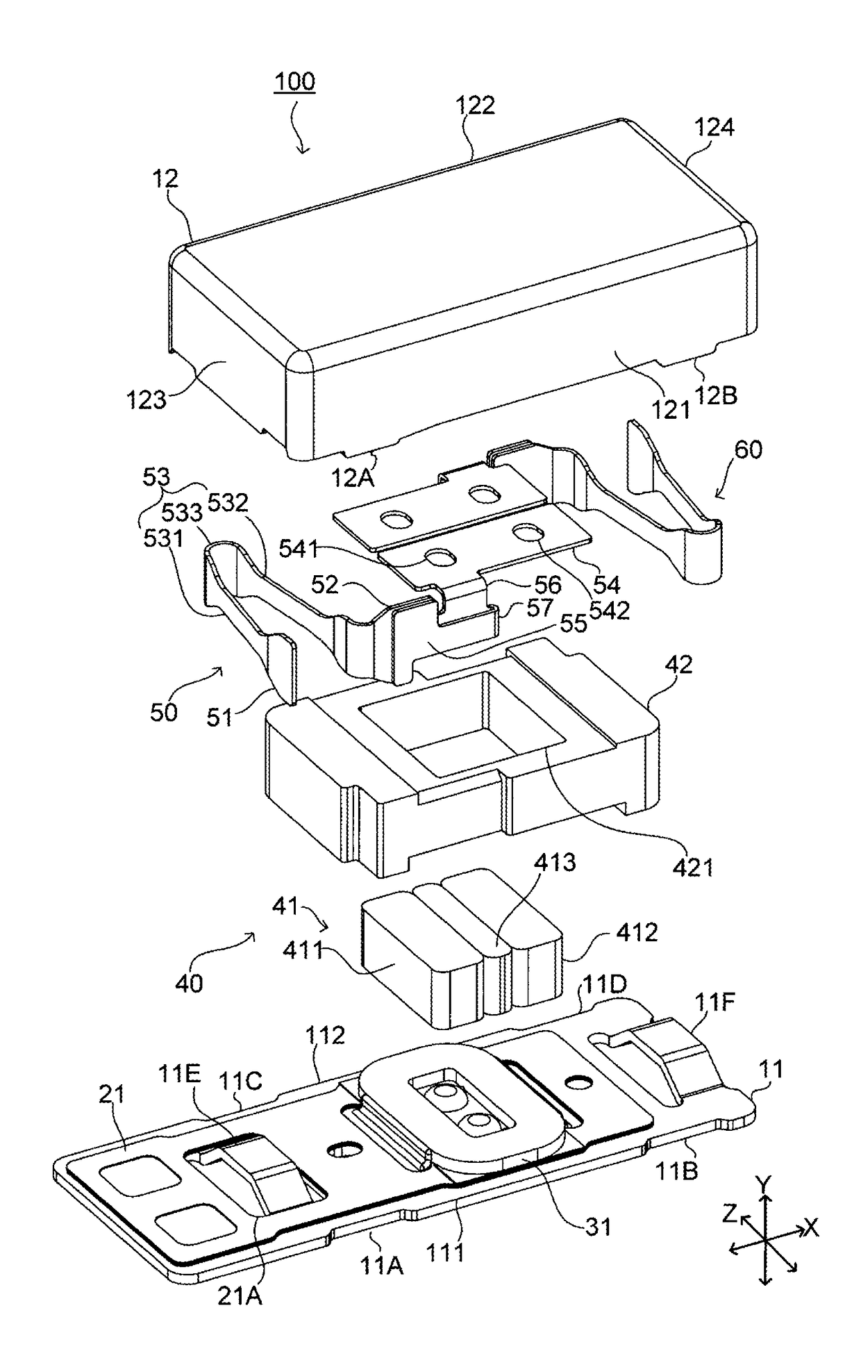
[0028]FIG. 1 is an exploded perspective view of a vibration motor according to a first embodiment of the present invention.

[0029]In FIG. 1, the left-right direction (one direction) is defined as a first direction, which is represented as the X-direction. The up-down direction, which is perpendicular to the first direction, is represented as the Y-direction. For example, in FIG. 1, upward along the plane of FIG. 1 is upward in the up-down direction (Y-direction). A second direction that is perpendicular to the first direction and the up-down direction is represented as the Z-direction. The same definitions apply to other figures. However, these definitions of directions do not apply to positional relationships and directions when the vibration motor is disposed in an actual device.

1-1. Overall Structure of Vibration Motor

[0030]A vibration motor 100 according to the present embodiment includes a base 11, a substrate 21, a coil 31, a vibrating body 40, an elastic mem...

second embodiment

2. Second Embodiment

[0076]Next, a second embodiment of the present invention will be described. FIG. 9 is an exploded perspective view of a vibration motor 200 according to the second embodiment of the present invention.

[0077]The vibration motor 200 illustrated in FIG. 9 includes a base 71, a cover 72, a substrate 73, a coil 74, a vibrating body 80, damper members 851 and 852, a top plate portion 90, elastic members 91 and 92, and reinforcement plates 95 to 98.

[0078]The base 71 and the substrate 73 extend in the first direction (X-direction). The substrate 73 is disposed on the base 71. The coil 74 is disposed on the substrate 73. The base 71 and the cover 72 constitute a casing. The casing, the substrate 73, and the coil 74 constitute a stationary portion. That is, the vibration motor 200 includes a stationary portion that includes the casing and the coil 74.

[0079]The vibrating body 80 includes a magnet 81 and a weight 82. The weight 82 is made of, for example, a tungsten alloy. Th...


PUM


Abstract

A vibration motor includes a stationary portion including a casing and a coil; a vibrating body including a weight and a magnet, the vibrating body being supported so as to be vibratable in one direction relative to the stationary portion; an elastic member located between the stationary portion and the vibrating body; and a top plate portion that is disposed above the vibrating body in an up-down direction that is perpendicular to the one direction. The magnet is disposed above the coil, and the top plate portion faces the magnet in the up-down direction. The magnet includes a set of first magnets that generate magnetic forces that are opposite to each other in the up-down direction and one or more second magnets that are interposed between the first magnets and each generate a magnetic force in the one direction.

Description

CROSS REFERENCE TO RELATED APPLICATIONS[0001]This application claims the benefit of priority to Japanese Patent Application No. 2016-145463 filed on Jul. 25, 2016. The entire contents of this application are hereby incorporated herein by reference.BACKGROUND OF THE INVENTION1. Field of the Invention[0002]The present invention relates to a vibration motor.[0003]2. Description of the Related Art[0004]Vibration motors have been used in various devices, such as smartphones. An example of existing vibration motors is disclosed in CN 202435225 U.[0005]The vibration motor described in CN 202435225 U includes a vibrating body, which includes two magnets, and a coil, which is fixed to a casing. When driving the vibration motor, a magnetic field is generated between the magnets and the coil, and the vibrating body vibrates. The vibration motor described in CN 202435225 U further includes a top plate portion. The top plate portion is disposed above the vibrating body in an up-down direction th...

Claims


Application Information

Patent Timeline
IPC IPC(8): B06B1/04H02K1/06H02K5/04H02K33/00
CPCB06B1/045H02K5/04H02K1/06H02K33/00H02K1/34H02K33/16H02K33/02H02K35/02
Inventor AKANUMA, TOMOHIROOI, MITSURUMORI, TAKASHINAKAZAWA, SATOSHI
Owner SANYO SEIMITSU
Why Eureka
Try Eureka