Head module and liquid jetting apparatus including the same

a liquid jetting apparatus and head module technology, applied in the field of head modules, can solve the problems that the substrate of the carriage might hinder or inhibit the radiation of heat, and achieve the effect of preventing heat radiation by the heat spreader

Active Publication Date: 2018-01-25
BROTHER KOGYO KK
View PDF3 Cites 12 Cited by
  • Summary
  • Abstract
  • Description
  • Claims
  • Application Information

AI Technical Summary

Benefits of technology

[0032]According to the present disclosure, the rigid substrate and the heat spreader are arranged side by side in the short direction of the nozzle surface (second direction), and the thickness of the rigid substrate is along the short direction of the nozzle surface (second direction). With this, the overlapping of the rigid substrate and the heat spreader in the attaching direction is made to be small as much as possible (this configuration also encompasses such a configuration wherein the rigid substrate and the heat spreader do not overlap with each other at all in the attaching direction), thereby making it possible to prevent the heat radiation by the heat spreader from being hindered by the rigid substrate. Further, this configuration is capable of preventing or restraining the size of the head module, in the alignment direction of the nozzles (the longitudinal direction of the nozzle surface, first direction as described above), from becoming large, than in a case wherein the rigid substrate and the heat spreader are arranged side by side in the longitudinal direction of the nozzle surface (first direction).

Problems solved by technology

Therefore, there is such a fear that the carriage substrate might hinder or inhibit the radiation of the heat by the heat sink.

Method used


Image

  • Head module and liquid jetting apparatus including the same
  • Head module and liquid jetting apparatus including the same
  • Head module and liquid jetting apparatus including the same

Examples


Embodiment Construction

[0052]In the following, an explanation will be given about an embodiment of the present disclosure.

[0053]

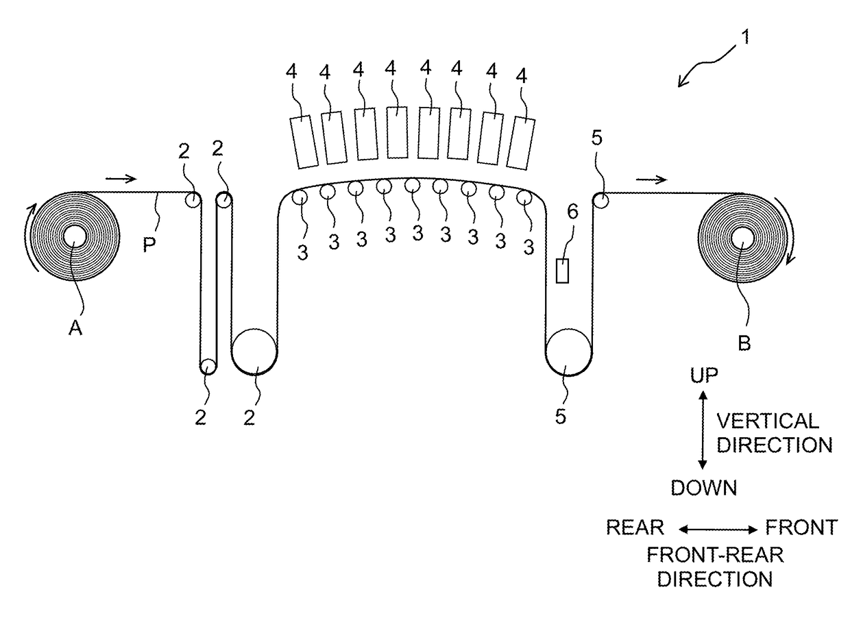
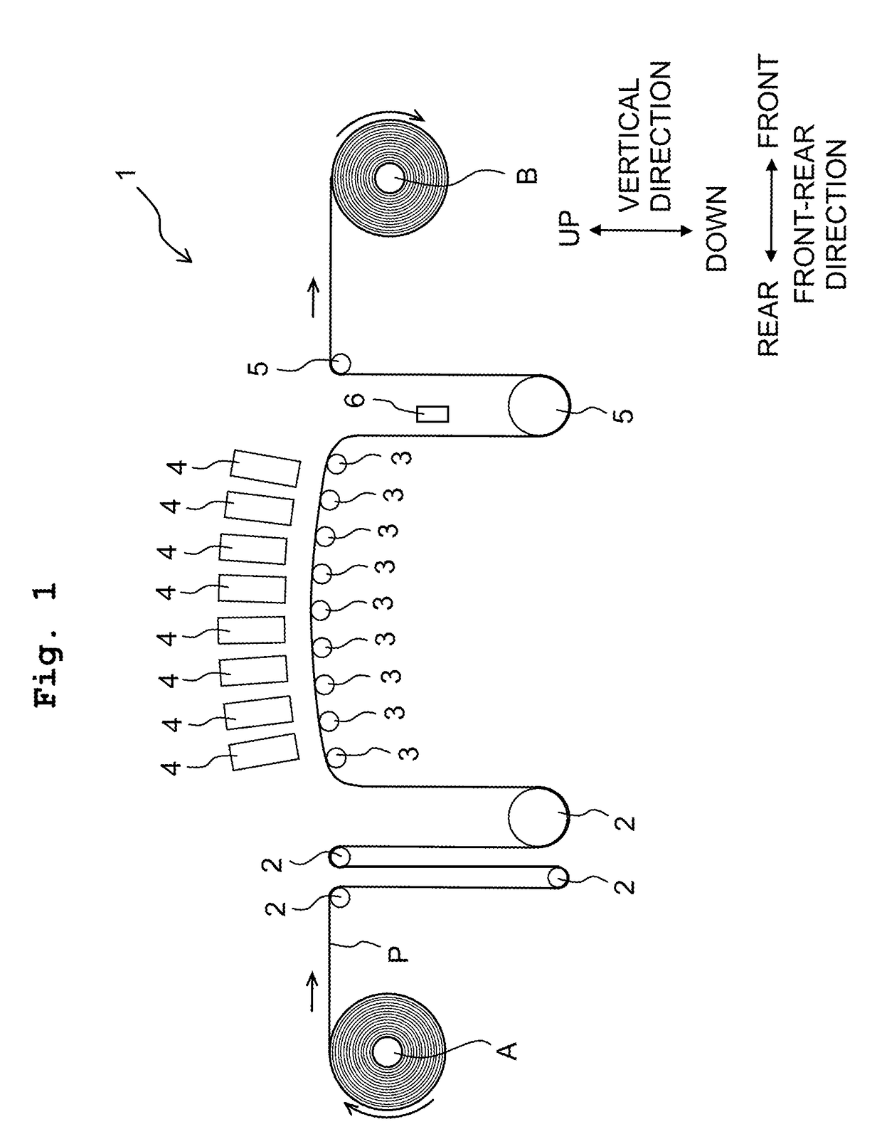
[0054]As depicted in FIG. 1, a printing apparatus 1 as a liquid jetting apparatus has a plurality of upstream rollers 2, nine pieces of supporting roller 3, eight pieces of line head 4, a plurality of downstream rollers 5, and a UV irradiating device 6. In the front-rear direction, the plurality of supporting rollers 3 and the eight line heads 4 are located in front of the plurality of upstream rollers 2, and the plurality of downstream rollers 5 are located in front of the plurality of supporting rollers 3 and the eight line heads 4.

[0055]The plurality of upstream rollers 2 convey a rolled paper P wound around a circular tube A. The plurality of upstream rollers 2 are apart from each other in the front-rear direction, and are apart from each other in the vertical direction. The rolled paper P is conveyed in a forward direction while being bent by the plurality of upstream roller...


PUM


Abstract

There is provided a head module including: a head which has an inlet, a plurality of nozzles, and a plurality of driving elements, and in which the nozzles are aligned in rows in a longitudinal direction of a nozzle surface orthogonal to a attaching/detaching direction of the head module; a plurality of driver ICs; a heat spreader; a flexible substrate; and a rigid substrate. In the attaching/detaching direction, the driver ICs are arranged between the head and the heat spreader; the rigid substrate and the head are arranged side by side in the attaching/detaching direction; the rigid substrate and the heat spreader are arranged side by side in a short direction of the nozzle surface; and the rigid substrate has a thickness along the short direction of the nozzle surface.

Description

CROSS REFERENCE TO RELATED APPLICATION[0001]The present application claims priority from Japanese Patent Application No. 2016-144462 filed on Jul. 22, 2016 the disclosure of which is incorporated herein by reference in its entirety.BACKGROUNDField of the Invention[0002]The present invention relates to a head module constructing a liquid jetting apparatus, and to a liquid jetting apparatus provided with the head module.Description of the Related Art[0003]Conventionally, there is known a head module provided with a recording head which jets (discharges) an ink from nozzles formed in a lower surface (hereinafter referred to as a “nozzle surface”) of the recording head, two driving ICs, a circuit board (wiring board) having the two driving ICs, a heat sink and a carriage substrate. In this conventional head module, the two driving ICs arranged side by side in a one horizontal direction are located to be above the recording head. Further, the heat sink extending across or over the two dr...

Claims


Application Information

Patent Timeline
Patent Type & Authority Applications(United States)
IPC IPC(8): B41J2/045B41J2/14B41J2/16
CPCB41J2/0455B41J2/04541B41J2002/14435B41J2/14427B41J2/1648B41J2002/14362B41J2002/14419B41J2002/14459B41J2202/08B41J2202/21B41J2/14201B41J2/18B41J2/04515B41J2202/20B41J29/377
Inventor ISHIZAKI, HIROTOSHI
Owner BROTHER KOGYO KK
Why Eureka
Try Eureka