Method and system for controlling water injection

a technology of water injection and water injection chamber, which is applied in the direction of machines/engines, mechanical equipment, non-fuel substance addition to fuel, etc., can solve the problems of engine being more knock-limited at high loads, reducing the fuel economy benefit of the transition, and not realizing the optimal fuel economy gain associated with water usage, etc., to achieve the effect of reducing engine emissions, reducing engine emissions, and increasing fuel economy and engine performan

Active Publication Date: 2018-01-25
FORD GLOBAL TECH LLC
View PDF0 Cites 5 Cited by
  • Summary
  • Abstract
  • Description
  • Claims
  • Application Information

AI Technical Summary

Benefits of technology

[0002]Internal combustion engines may include water injection systems that inject water into a plurality of locations, such as into an intake manifold, upstream of engine cylinders, or directly into engine cylinders. Engine water injection provides various benefits such as an increase fuel economy and engine performance, as well as a decrease in engine emissions. In particular, when water is injected into the engine intake or cylinders, heat is transferred from the intake air and / or engine components to evaporate the water, leading to charge cooling. Injecting water into the intake air (e.g., in the intake manifold) lowers both the intake air temperature and a temperature of combustion at the engine cylinders. By cooling the intake air charge, a knock tendency may be decreased without enriching the combustion air-fuel ratio. This may also allow for a higher compression ratio, advanced ignition timing, improved wide-open throttle performance, and decreased exhaust temperature. As a result, fuel efficiency is increased. Additionally, greater volumetric efficiency may lead to increased torque. Furthermore, lowered combustion temperature with water injection may reduce NOx emissions, while a more efficient fuel mixture (less enrichment) may reduce carbon monoxide and hydrocarbon emissions.
[0005]The inventors herein have recognized that the fuel economy benefits of an engine configured with water injection may be better leveraged through integration with a continuously variable transmission (CVT). In particular, the CVT may enable the engine speed and load to be adjusted based on water usage (and availability) while maintaining the power output of the engine. In one example, fuel economy may be improved by a method for an engine configured with water injection, the engine coupled with a continuously variable transmission (CVT), the method comprising: for a driver demanded power level, comparing fuel economy without water injection to fuel economy with water injection at a first adjusted engine speed-load; and in response to a higher than threshold improvement in the fuel economy with water injection at the adjusted engine speed-load, injecting an amount of water into the engine and changing to the first adjusted engine speed-load via the continuously variable transmission (CVT). In this way, an engine can be operated with water injection while providing an improved fuel economy for a given driver demand by increasing the maximum load that can be achieved without knocking, or in other words, by increasing the knock limit.
[0007]In this way, fuel economy benefits can be improved. The technical effect of integrating water injection technology in a vehicle having a CVT transmission is that for a given driver demanded power, the benefits of the water injection can be better leveraged. In particular, the engine speed and torque for a given driver demanded power can be adjusted to reduce knock limitations at higher loads to increase the maximum load, and reduce friction losses at lower loads, while accounting for changes in knock limits due to water injection properties. The technical effect of assessing the fuel economy benefit of switching water injection states with the fuel penalty associated with operating at the engine speed-load profile corresponding to a selected water injection state is that frequent switching between water injection states can be reduced. While operating the engine with the more efficient and cost-effective water injection state, CVT adjustments can be used to extend engine operation with water injection despite changes in driver or wheel torque demand, and for conditions where the benefit of water injection is small, CVT adjustments can be used to extend engine operation without water injection despite changes in driver or wheel torque demand. By optimizing water usage, the benefits of water injection can be extended over a longer portion of a drive cycle, even when water availability is limited.

Problems solved by technology

However the inventors herein have recognized potential issues with such approaches.
As one example, the optimal fuel economy gain associated with water usage may not be realized due to the fixed gear ratio of the transmission.
However, when transitioning between operating with or without water injection, there may be engine limitations experienced at the associated engine speed-load that may reduce the fuel economy benefit of the transition.
As an example, when water injection is not being used, the engine may become more knock-limited at high loads.
Another issue is that frequent changes in operator pedal demand may cause the engine load to move back and forth, leading to frequent switching on and off of water injection.
Excessive switches can degrade fuel economy due to losses incurred during transitions, and may degrade the life of the parts, and may cause air-fuel disturbances that move away from ideal stoichiometry.
As an example, when operating with water injection inactive, the engine may be knock limited at lower loads than when water injection is active.
Therefore, to address knock anticipated while operating without water injection, an engine controller may need to actuate the CVT to increase the engine speed while decreasing the engine load so as to maintain the demanded engine power output, which may or may not provide a net cost benefit.

Method used


Image

  • Method and system for controlling water injection
  • Method and system for controlling water injection
  • Method and system for controlling water injection

Examples


Embodiment Construction

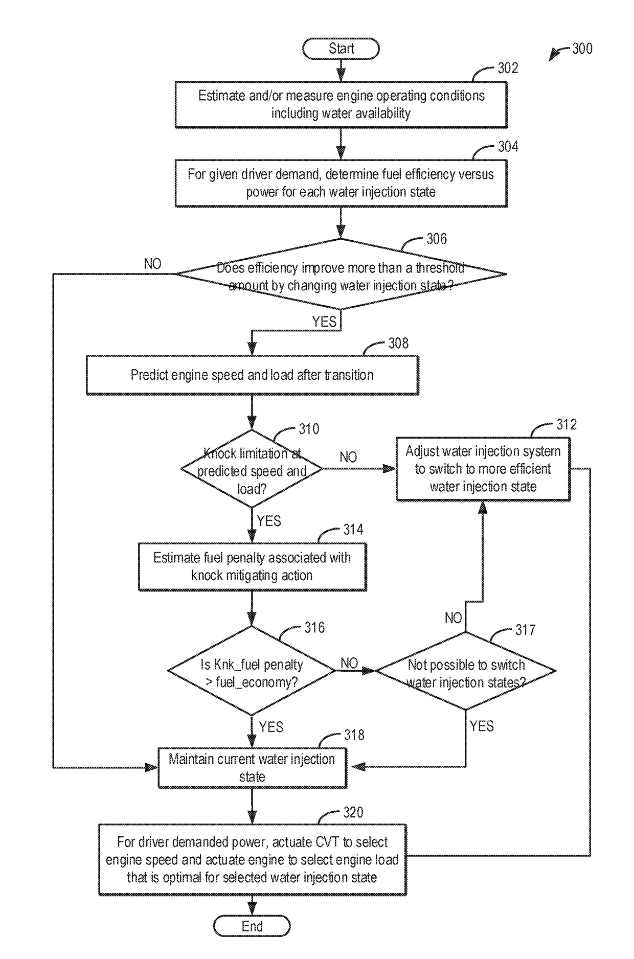
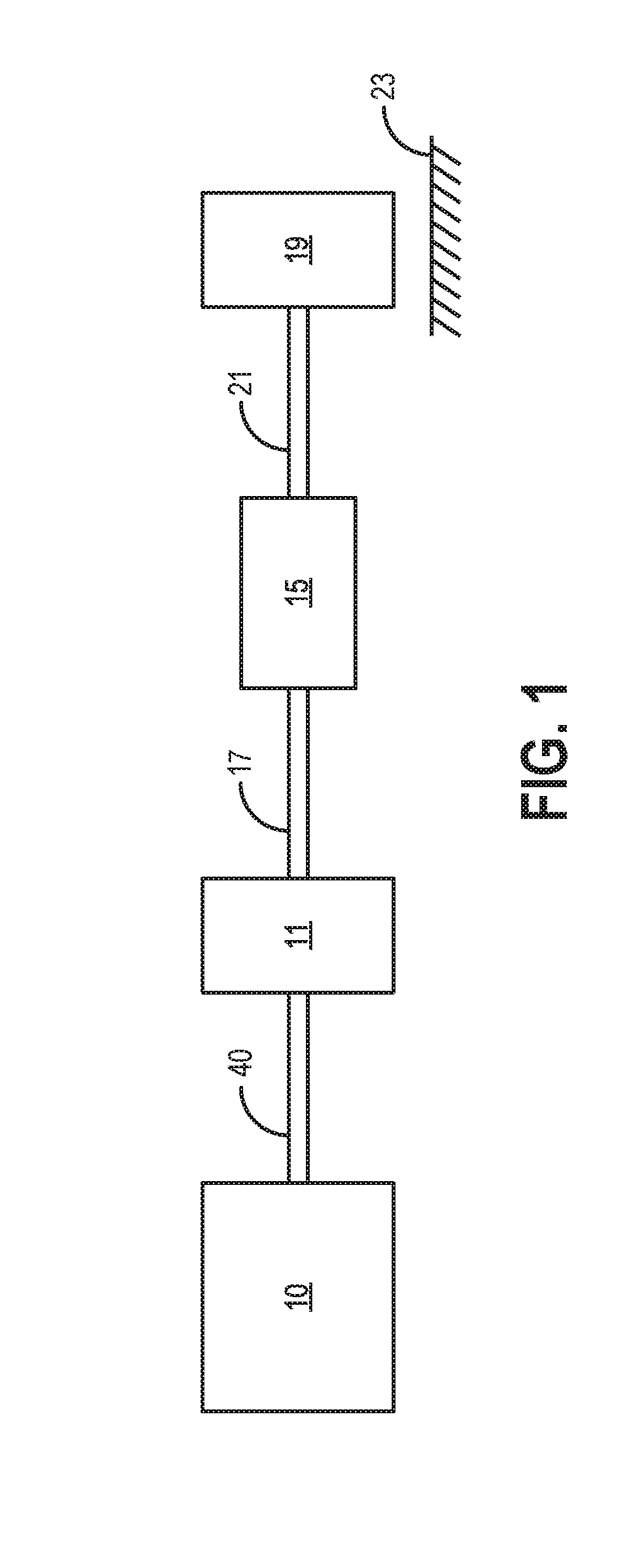
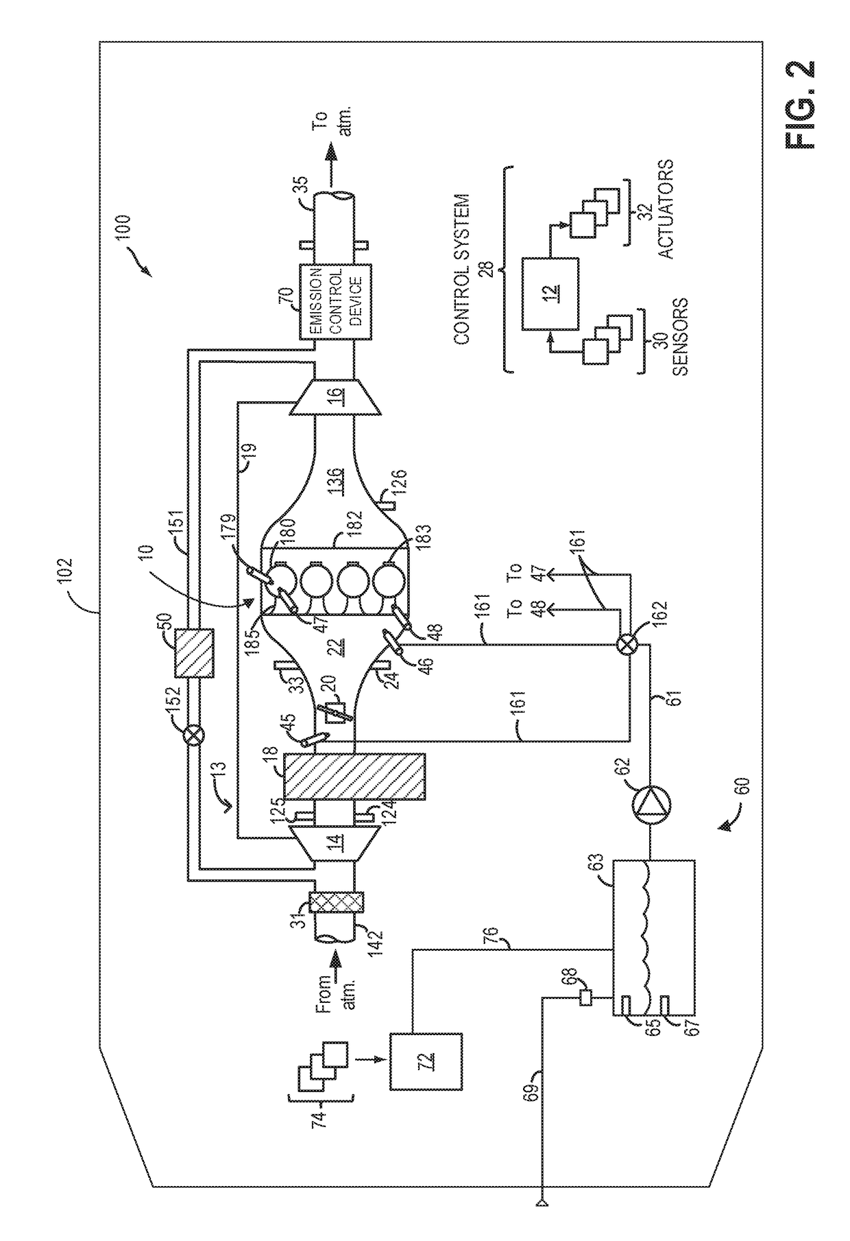
[0014]The following description relates to systems and methods for improving fuel economy in a vehicle having a continuously variable transmission (herein also referred to as a CVT), such as the powertrain of FIG. 1. The vehicle may include an engine system configured for water injection, as described with reference to the engine system of FIG. 2. A controller may be configured to perform a control routine, such as the example routine of FIG. 3, to select a water injection state (active or inactive) based on water availability while adjusting an engine speed-load profile via adjustments to a speed ratio of the CVT to better leverage the fuel economy benefits of water injection. An example map that may be used by the controller to select whether to maintain or transition between water injection states is shown with reference to FIG. 4. An example engine operation with water usage and CVT adjustments is shown at FIG. 5. In this way, water injection technology can be integrated and syn...


PUM


Abstract

Methods and systems are provided for integrating engine water injection technology with a CVT transmission. Responsive to a driver demand, a controller may determine whether to maintain a current water injection state or transition to an alternate water injection state based on each of the efficiency of the transition, water availability, and any engine limitations that may be incurred at the engine speed-load following the transition. To improve the net fuel economy benefit while addressing the engine limitation, the water injection state transition may be combined with a CVT adjusted engine speed-load regime, while maintaining engine power output.

Description

FIELD[0001]The present description relates generally to methods and systems for controlling water usage of an engine coupled with a continuously variable transmission (CVT).BACKGROUND / SUMMARY[0002]Internal combustion engines may include water injection systems that inject water into a plurality of locations, such as into an intake manifold, upstream of engine cylinders, or directly into engine cylinders. Engine water injection provides various benefits such as an increase fuel economy and engine performance, as well as a decrease in engine emissions. In particular, when water is injected into the engine intake or cylinders, heat is transferred from the intake air and / or engine components to evaporate the water, leading to charge cooling. Injecting water into the intake air (e.g., in the intake manifold) lowers both the intake air temperature and a temperature of combustion at the engine cylinders. By cooling the intake air charge, a knock tendency may be decreased without enriching ...

Claims


Application Information

Patent Timeline
Patent Type & Authority Applications(United States)
IPC IPC(8): B60W30/18B60W10/06F02M25/022B60W10/101F02B47/02F02M25/025
CPCB60W30/18F02B47/02F02M25/025B60W2710/1005B60W10/101B60W10/06F02M25/0227B60W10/107B60W30/1882B60W2710/06Y02T10/12
Inventor LEONE, THOMAS G.MILLER, KENNETH JAMES
Owner FORD GLOBAL TECH LLC
Why Eureka
Try Eureka