Iodine propellant RF ion thruster with RF cathode

a technology of iodine propellant and rf cathode, which is applied in the direction of electrical equipment, using plasma, electric discharge tubes, etc., can solve the problems of limiting the life of the cathode, and achieve the effect of increasing the electron output of the rf cathode and increasing the surface area of the grid pla

Inactive Publication Date: 2018-01-25
BUSEK
View PDF0 Cites 15 Cited by
  • Summary
  • Abstract
  • Description
  • Claims
  • Application Information

AI Technical Summary

Benefits of technology

[0015]The method may further include increasing the electron output of the RF cathode by placing at least one grid plate proximate the RF cathode and increasing the surface area of the grid plate. There may be two conductive plates with orifices therethough, one plate supplied with a positive voltage and the other plate supplied with a negative voltage.

Problems solved by technology

The hollow cathode includes an oxide insert which is consumed when the cathode is operated limiting the life of the cathode.
Still, in testing, a heater was required for proper operation and such a hollow cathode design may impart constraints for certain types of missions where power is limited or rapid start of the cathode is required.

Method used


Image

  • Iodine propellant RF ion thruster with RF cathode
  • Iodine propellant RF ion thruster with RF cathode
  • Iodine propellant RF ion thruster with RF cathode

Examples


Embodiment Construction

[0027]Aside from the preferred embodiment or embodiments disclosed below, this invention is capable of other embodiments and of being practiced or being carried out in various ways. Thus, it is to be understood that the invention is not limited in its application to the details of construction and the arrangements of components set forth in the following description or illustrated in the drawings. If only one embodiment is described herein, the claims hereof are not to be limited to that embodiment. Moreover, the claims hereof are not to be read restrictively unless there is clear and convincing evidence manifesting a certain exclusion, restriction, or disclaimer.

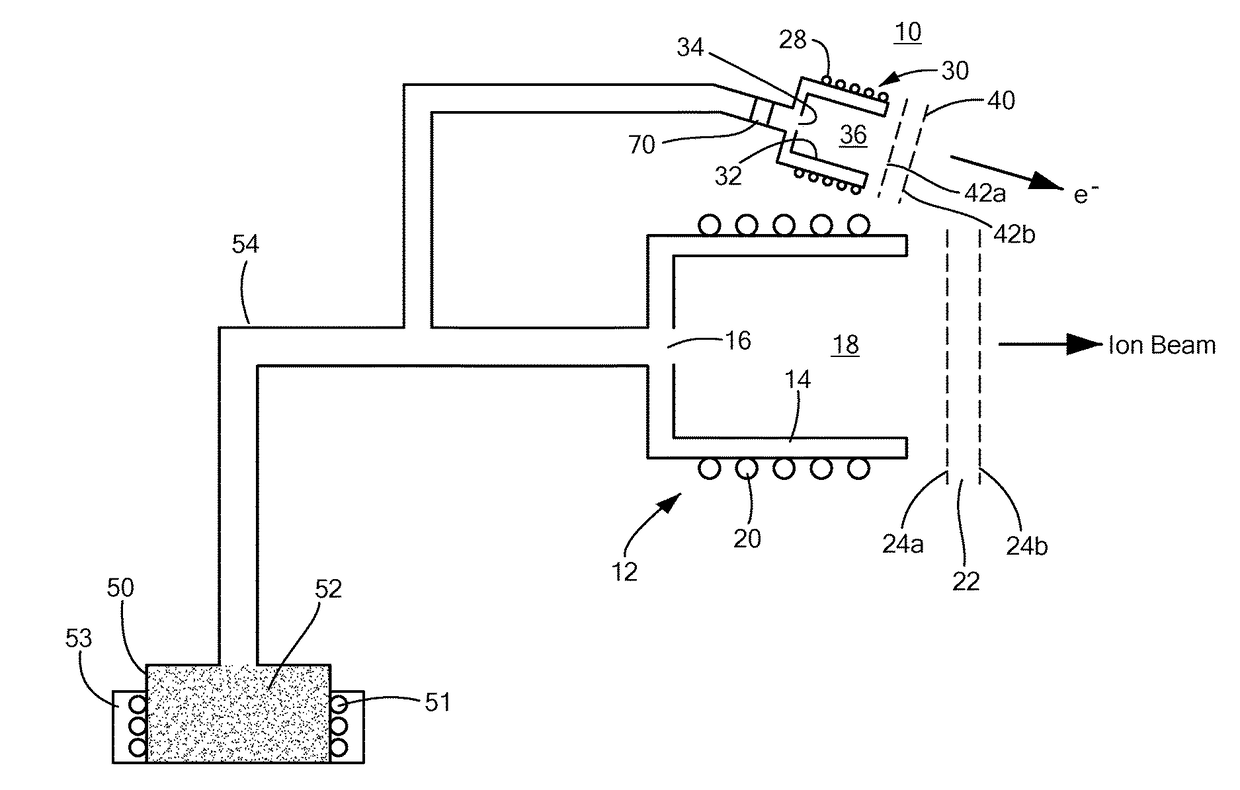
[0028]FIG. 1 shows an exemplary RF ion thruster system 10 with RF ion thruster 12 including ceramic discharge chamber 14 having a gas inlet 16 and an outlet 18. Coil 20 is disposed about chamber 14 and conductive grid subsystem 22 proximate discharge chamber outlet 18 typically includes conductive plates 24a, 24b with orifi...


PUM


Abstract

A thrust producing system includes an RF ion thruster with a discharge chamber having a gas inlet and an outlet, and a coil about the discharge chamber. The system further includes an RF cathode proximate the discharge chamber outlet of the RF ion thruster for ion beam neutralization. The RF cathode includes a discharge chamber having a gas inlet and an outlet and a coil about the discharge chamber. A tank for containing iodine in solid form and a heater associated with said tank to produce iodine vapor. A feed subsystem fluidly couples the tank with the RF ion thruster discharge chamber gas inlet and with the RF cathode discharge chamber gas inlet.

Description

RELATED APPLICATIONS[0001]This application claims benefit of and priority to U.S. Provisional Application Ser. No. 62 / 319,550 filed Apr. 7, 2016, under 35 U.S.C. §§119, 120, 363, 365, and 37 C.F.R. §1.55 and §1.78, which is incorporated herein by this reference.GOVERNMENT RIGHTS[0002]This invention was made with U.S. Government support under Contract No. NNX15CC90C awarded by the National Aeronautics and Space Administration (NASA). The Government may have certain rights in the subject invention.FIELD OF THE INVENTION[0003]The subject invention relates to radio frequency ion thrusters.BACKGROUND OF THE INVENTION[0004]Radio frequency ion thrusters typically operate on a propellant such as xenon and include a hollow cathode to neutralize the ion beam emitted by the discharge chamber of the ion generator. See U.S. Pat. No. 9,060,412 incorporated herein by this reference.[0005]The hollow cathode includes an oxide insert which is consumed when the cathode is operated limiting the life of...

Claims


Application Information

Patent Timeline
Patent Type & Authority Applications(United States)
IPC IPC(8): F03H1/00
CPCF03H1/0031F03H1/0043F03H1/0012F03H1/0025H01J27/16
Inventor TSAY, MICHAELFRONGILLO, III, JOHN J.MODEL, JOSHUAZWAHLEN, JURG
Owner BUSEK
Why Eureka
Try Eureka