Bi-static radar system

a radar system and bi-static technology, applied in the field of bi-static radar system, can solve the problems of phase noise and range delay, and the difference in the start time of these waveforms

a radar system and bi-static technology, applied in the field of bi-static radar system, can solve the problems of phase noise and range delay, and the difference in the start time of these waveforms

US20180024233A1Active Publication Date: 2018-01-25APTIV TECH LTD

Image

  • Bi-static radar system
  • Bi-static radar system
  • Bi-static radar system

Examples


Embodiment Construction

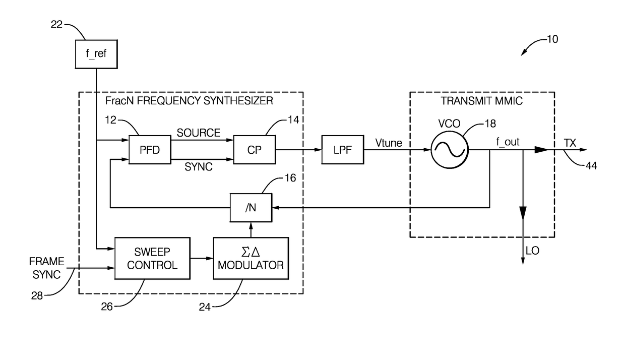
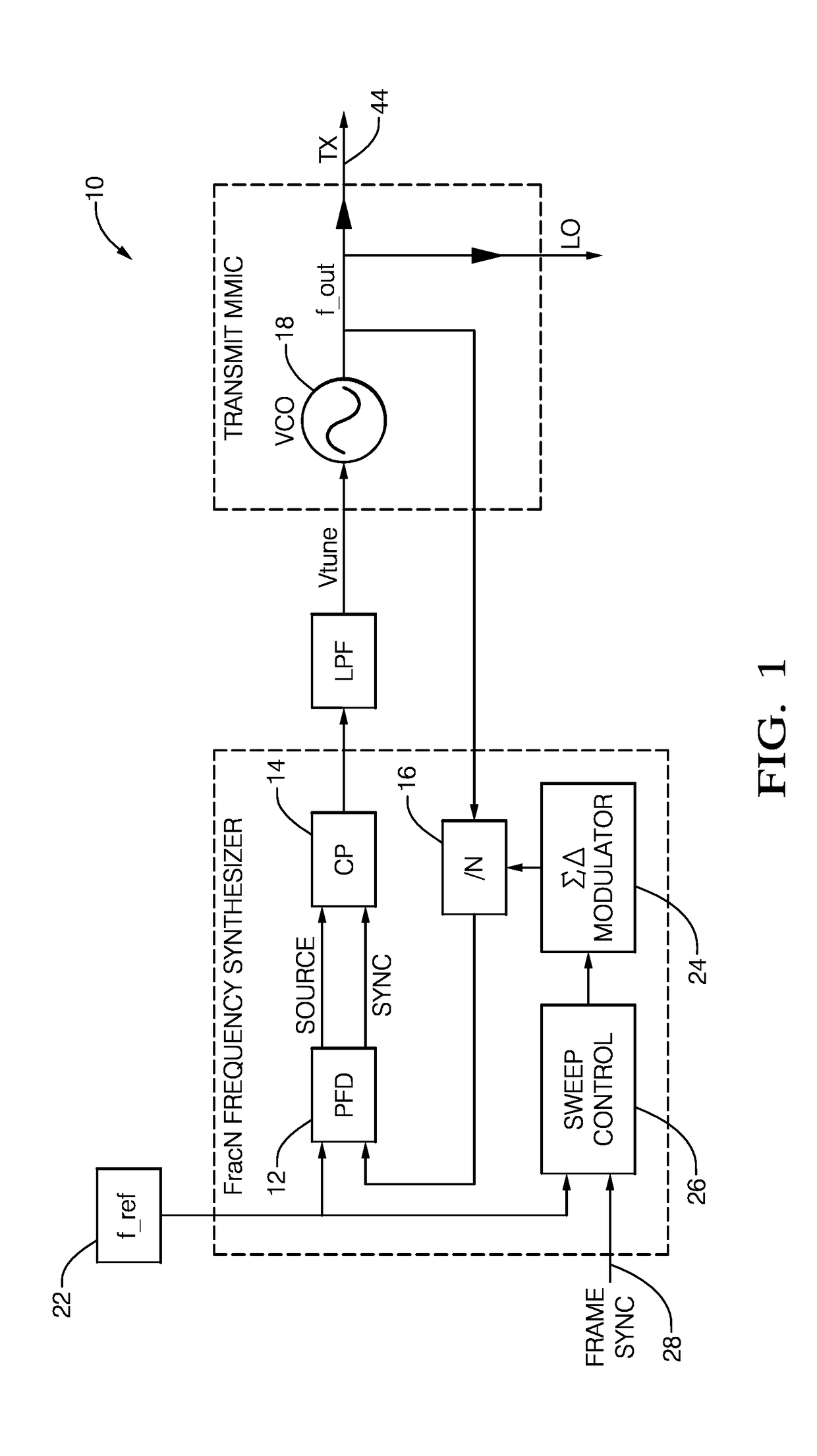
[0015]FIG. 1 illustrates a non-limiting example of a portion of a bi-static radar system, hereafter the system 10, which includes a phase-frequency detector, hereafter the PFD 12. The PFD 12 provides an output that controls or commands a charge-pump 14 (labeled CP) to either source or sink current, based upon edges received from the reference and VCO feedback signals. The block labeled ‘ / N’ is a divide-by-N divider, hereafter N-divider 16, which is used to divide down f_out which is the output of a voltage-controlled-oscillator 18 or VCO 18 that is feedback to the PFD 12. The phase-lock-loop (PLL) that includes the PFD 12 and the VCO 18 will try to lock the phase of the divided signal to a reference frequency (f_ref) output by a reference oscillator 22. The sigma delta (ΣΔ) modulator 24 varies the value of N that characterizes the operation of the N-divider 16 to provide various fractional divisor values. The output of a sweep-control 26 will vary the fractional N-divider value over...


PUM


Abstract

A bi-static radar system configured for coherent detection of a radar-signal includes a plurality of radar-transceivers, a controller, and a communications device. The plurality of radar-transceivers is characterized as physically spaced apart with respect to each other. The controller is in communication with the each of the radar-transceivers and is configured to coherently operate each of the radar-transceivers. The communications device communicates both a reference-clock signal and a frame-sync signal from the controller to each of the plurality of radar-transceivers whereby the plurality of radar-transceivers operate coherently. Alternatively, the system may include a reference-signal generator, a transmitter, and a plurality of receivers. The reference-signal generator generates a reference-signal characterized by a reference-frequency proportional to a fraction of a radar-frequency of a radar-signal transmitted. The transmitter generates the radar-signal at the radar-frequency based on the reference-signal. The plurality of receivers operates coherently to detect the radar-signal based on the reference-signal.

Description

CROSS-REFERENCE TO RELATED APPLICATION[0001]This application claims the benefit under 35 U.S.C. §119(e) of U.S. Provisional Patent Application No. 62 / 211,114, filed Aug. 28, 2015, the entire disclosure of which is hereby incorporated herein by reference.TECHNICAL FIELD OF INVENTION[0002]This disclosure generally relates to a bi-static radar system.BACKGROUND OF INVENTION[0003]Bi-static radar is useful for various purposes, including improved probability of detection, formation of a larger antenna aperture through the combination of signals received from multiple radar-transceiver, etc. An important motivation for larger antenna aperture, and perhaps the primary motivation for coherent bi-static radar, is much improved angle capability (accuracy and discrimination). Coherent radar-transceiver operation will provide improved performance for bi-static radar compared to those operating with independent VCOs. A known method to make multiple homodyne receivers coherent is to distribute th...

Claims


Application Information

Patent Timeline
25 Jan 2018
Publication
US20180024233A1
IPC
G01S13/00; G01S7/00
CPC
G01S13/003; G01S7/006; G01S7/032; G01S7/4008; G01S13/87
Inventors
SEARCY, JAMES F.; ROSSITER, RYAN K.