Communication apparatus, communication system, and communication method
- Summary
- Abstract
- Description
- Claims
- Application Information
AI Technical Summary
Benefits of technology
Problems solved by technology
Method used
Image
Examples
first embodiment
(1) First Embodiment
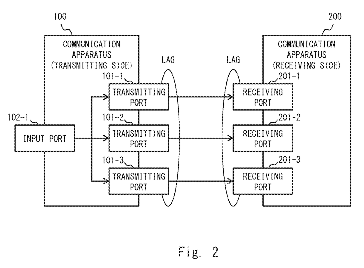
[0022]FIG. 2 shows a configuration example of a communication system according to this embodiment. The communication system shown in FIG. 2 includes a communication apparatus 100 (a first communication apparatus) and a communication apparatus 200 (a second communication apparatus) connected to each other by an LAG, and has a configuration in which packets are transmitted from the communication apparatus 100 to the communication apparatus 200. The communication apparatus 100 on the transmitting side includes three transmitting ports 101-1 to 101-3 constituting an LAG, and an input port 102-1. The input port 102-1 is a physical port from which packets to be transmitted are input. The transmitting ports 101-1 to 101-3 are physical ports from which the packets input from the input port 102-1 are transmitted to the communication apparatus 200, which is an apparatus on the other side, through corresponding physical links. Meanwhile, the communication apparatus 200 on t...
second embodiment
(2) Second Embodiment
[0025]In this embodiment, a configuration and an operation of the communication apparatus 100 according to the first embodiment are described in a more concrete manner. FIG. 3 shows a configuration example of a communication system according to this embodiment. The configuration of a communication apparatus 100 in the communication system shown in FIG. 3 differs from that in the first embodiment shown in FIG. 2. The communication apparatus 100 includes transmitting ports 101-1 to 101-3, an input port 102-1, a switch 103, a low-priority queue 104, a high-priority queue 105, a packet identifier assignment unit 106, and a distribution destination determination unit 107. Note that although FIG. 3 shows the communication apparatus 100 including one input port 102-1 and three transmitting ports 101-1 to 101-3, the communication apparatus 100 may include other input ports and other transmitting ports. Further, although FIG. 3 shows a communication apparatus 200 includi...
third embodiment
(3) Third Embodiment
[0038]In the second embodiment, packets to which the identifier B is assigned (i.e., packets that are other than the specific packets and have the predetermined packet length or longer) are not distributed to the specific transmitting port. Therefore, there is a high possibility that the amount of data transmission (the amount of flow) in the specific transmitting port could be relatively small compared to those of the other transmitting ports. Therefore, it is conceivable that the frequency band of the physical link is not effectively used.
[0039]In this embodiment, the frequency band of the physical link is effectively used by adjusting the distribution destination of packets to which the identifier A is assigned (packets that are other than the specific packets and have a packet length shorter than the predetermined packet length) based on the amount of data transmission (hereinafter referred to as a “data transmission amount”) in each of the transmitting ports...
PUM
 Abstract
Description
Claims
Application Information
 - R&D
- Intellectual Property
- Life Sciences
- Materials
- Tech Scout
- Unparalleled Data Quality
- Higher Quality Content
- 60% Fewer Hallucinations
Browse by: Latest US Patents, China's latest patents, Technical Efficacy Thesaurus, Application Domain, Technology Topic, Popular Technical Reports.
© 2025 PatSnap. All rights reserved.Legal|Privacy policy|Modern Slavery Act Transparency Statement|Sitemap|About US| Contact US: help@patsnap.com


