
Audio accessory for auditory prosthesis system that includes body-worn sound processor apparatus

a technology of body-worn sound processor and audio accessory, which is applied in the direction of instruments, artificial respiration, therapy, etc., can solve the problems of inability of other types of sound processor units to perform such noise-cancelation processing, inability of certain body-worn sound processor units to have beamforming capabilities, and inability to achieve the improved hearing performan

Inactive Publication Date: 2018-01-25
ADVANCED BIONICS AG
View PDF2 Cites 1 Cited by
  • Summary
  • Abstract
  • Description
  • Claims
  • Application Information

AI Technical Summary

Benefits of technology

The patent describes an auditory prosthesis system that includes a body-worn sound processor apparatus, a headpiece, and an audio accessory. The audio accessory is designed to improve the hearing performance of patients with cochlear implants by providing beamforming operations that remove unwanted noise from incoming audio. The system allows for improved noise cancellation processing and improved hearing performance even if certain components of the system do not have the necessary capabilities. The audio accessory can be interposed between the body-worn sound processor apparatus and the headpiece to achieve the beamforming effects. The technical effect of this patent is to provide an improved auditory prosthesis system that offers improved hearing performance to patients with cochlear implants while maintaining the use of conventional components.

Problems solved by technology

Unfortunately, other types of sound processor units may be unable to perform such noise-cancelation processing.
For example, certain body-worn sound processor units may not have beamforming capabilities.
Accordingly, these patients may be unable to achieve the improved hearing performance afforded by beamforming operations due to their choice to use a conventional body-worn sound processor unit.

Method used


Image

  • Audio accessory for auditory prosthesis system that includes body-worn sound processor apparatus
  • Audio accessory for auditory prosthesis system that includes body-worn sound processor apparatus
  • Audio accessory for auditory prosthesis system that includes body-worn sound processor apparatus

Examples


Embodiment Construction

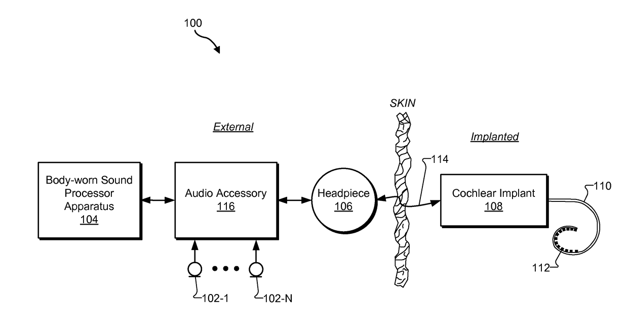
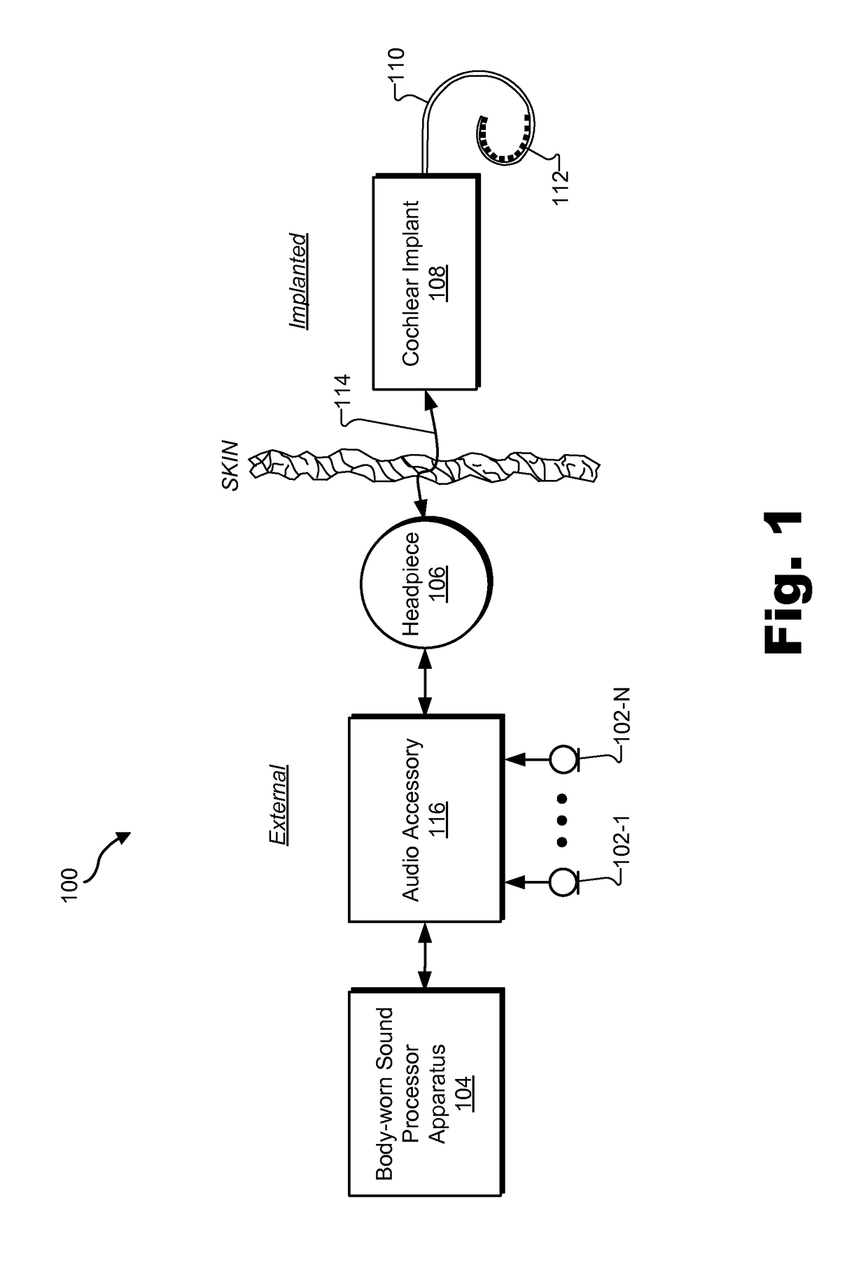
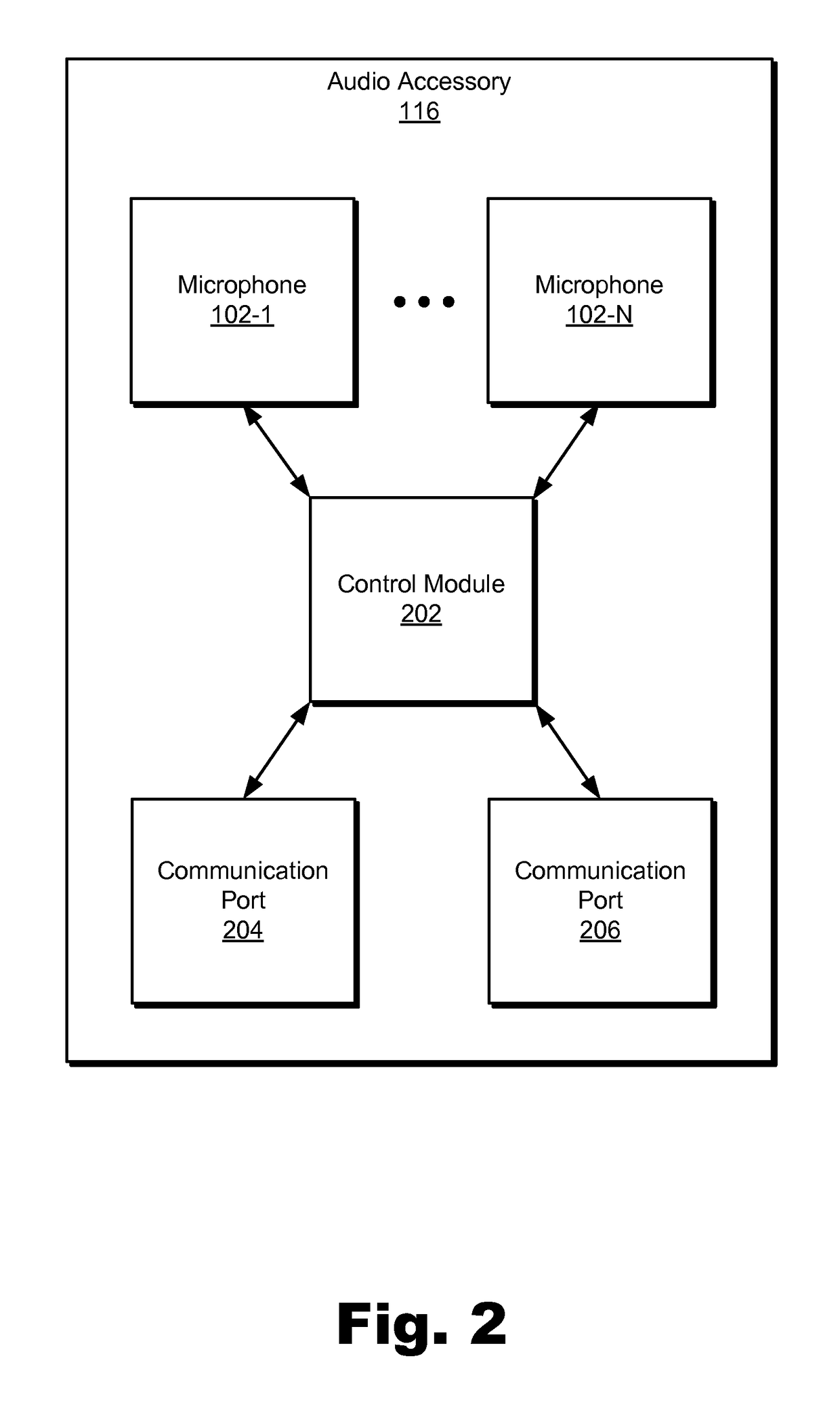
[0010]Auditory prosthesis systems are described herein. As will be described below, an exemplary auditory prosthesis system may include 1) a body-worn sound processor apparatus configured to be external to a patient and control an operation of a cochlear implant implanted within the patient, 2) a headpiece configured to be external to the patient and facilitate wireless coupling of the body-worn sound processor apparatus to the cochlear implant, and 3) an audio accessory configured to be external to the patient. In one example, the audio accessory may include a plurality of microphones that receive incoming audio and convert the incoming audio into a plurality of audio signals. In this example, the audio accessory may also include a first communication port that connects directly to a communication port of the body-worn sound processor apparatus by way of a first cable and a second communication port that connects directly to a communication port of the headpiece by way of a second ...


PUM


Abstract

An exemplary auditory prosthesis system includes an audio accessory configured to be external to a patient and that includes 1) a plurality of microphones that receive incoming audio and convert the incoming audio into a plurality of audio signals, 2) a first communication port that connects directly to a communication port of a body-worn sound processor apparatus by way of a first cable, 3) a second communication port that connects directly to a communication port of a headpiece by way of a second cable, and 4) a control module communicatively coupled to the plurality of microphones and the first and second communication ports and that generates a processed audio signal by processing the plurality of audio signals converted by the plurality of microphones from the incoming audio and provides the processed audio signal to the body-worn sound processor apparatus.

Description

BACKGROUND INFORMATION[0001]Many auditory prosthesis systems are capable of implementing noise-cancelation processing (e.g., beamforming) that improves the hearing performance of certain patients with hearing loss. For example, an auditory prosthesis system may include a behind-the-ear (“BTE”) sound processor unit located behind the ear of a patient. In this example, the BTE sound processor unit may include multiple microphones used to perform beamforming operations that remove unwanted noise from incoming audio.[0002]Unfortunately, other types of sound processor units may be unable to perform such noise-cancelation processing. For example, certain body-worn sound processor units may not have beamforming capabilities. Despite this deficiency, some patients may still choose a body-worn sound processor unit over a BTE sound processor unit for various reasons. As an example, some patients may need to use a body-worn sound processor unit to support the power requirements of older-genera...

Claims


Application Information

Patent Timeline
Patent Type & Authority Applications(United States)
IPC IPC(8): H04R25/00A61N1/372A61N1/36G10L21/0216A61N1/05
CPCH04R25/554H04R25/606G10L21/0216A61N1/0541A61N1/36038A61N1/37229H04R2225/67H04R2460/01G10L2021/02166A61N1/3787H04R25/04H04R25/405H04R25/55H04R25/556H04R25/558
Inventor MEIER, ROGER S.PALMER, LOGAN P.CHANG, DIANE H.WALSH, THOMAS P.
Owner ADVANCED BIONICS AG
Learn More