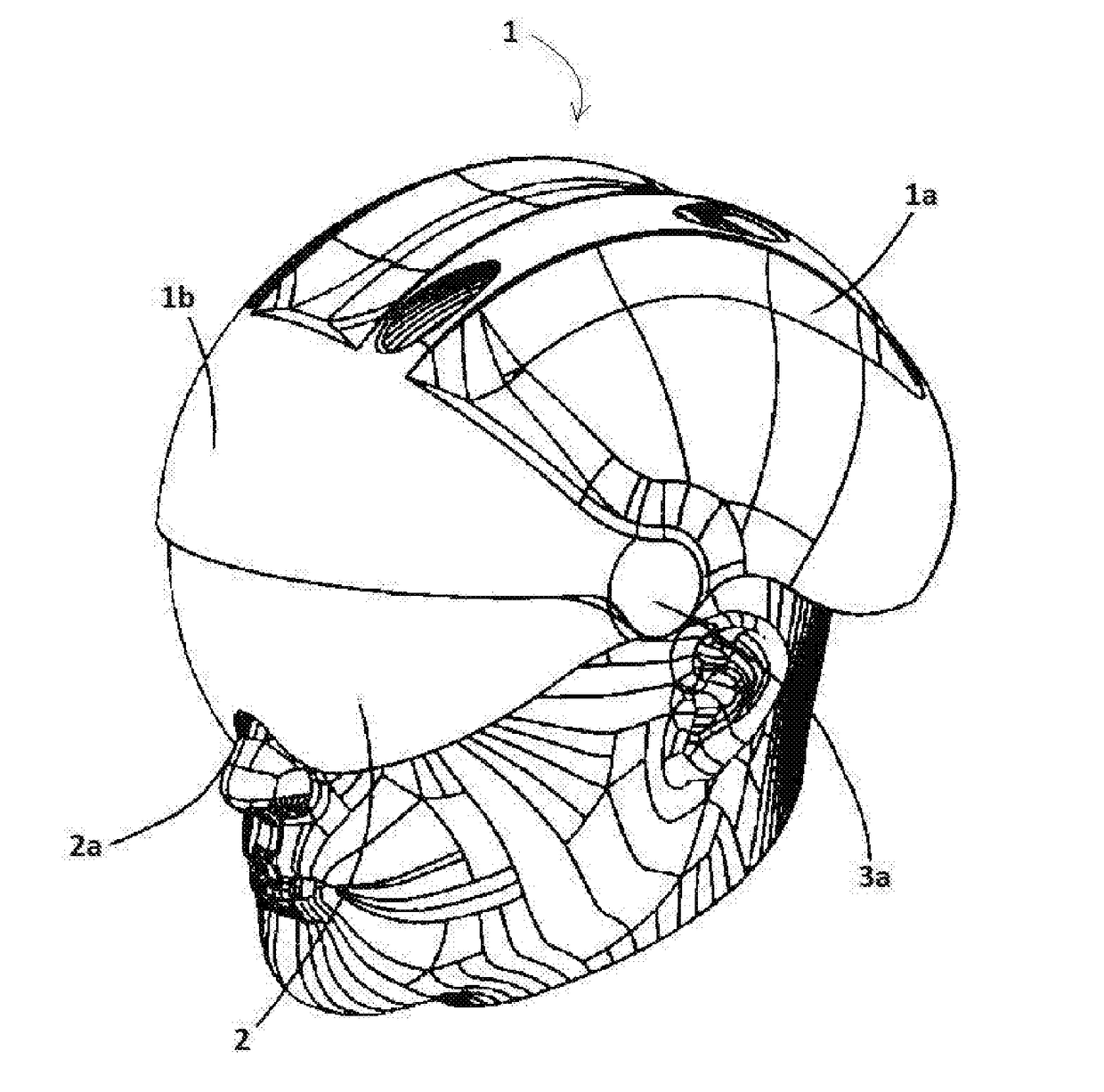
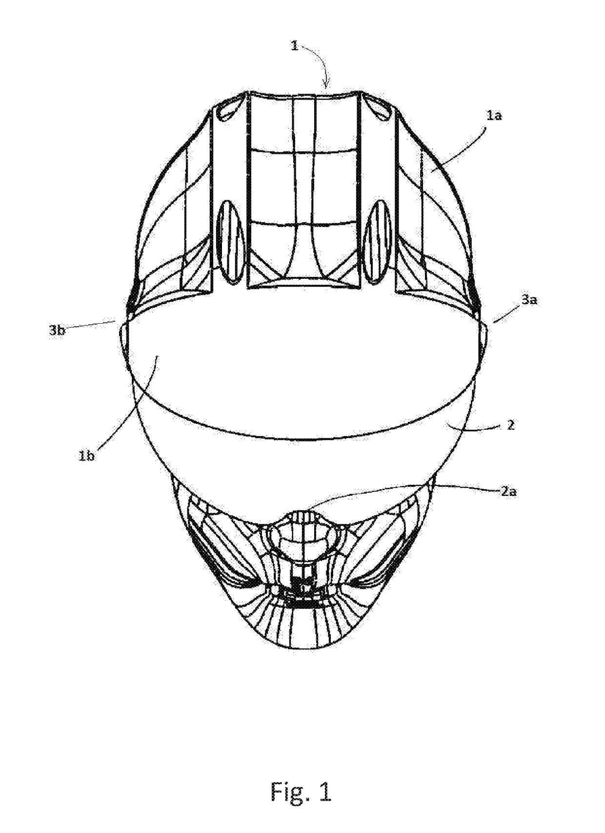
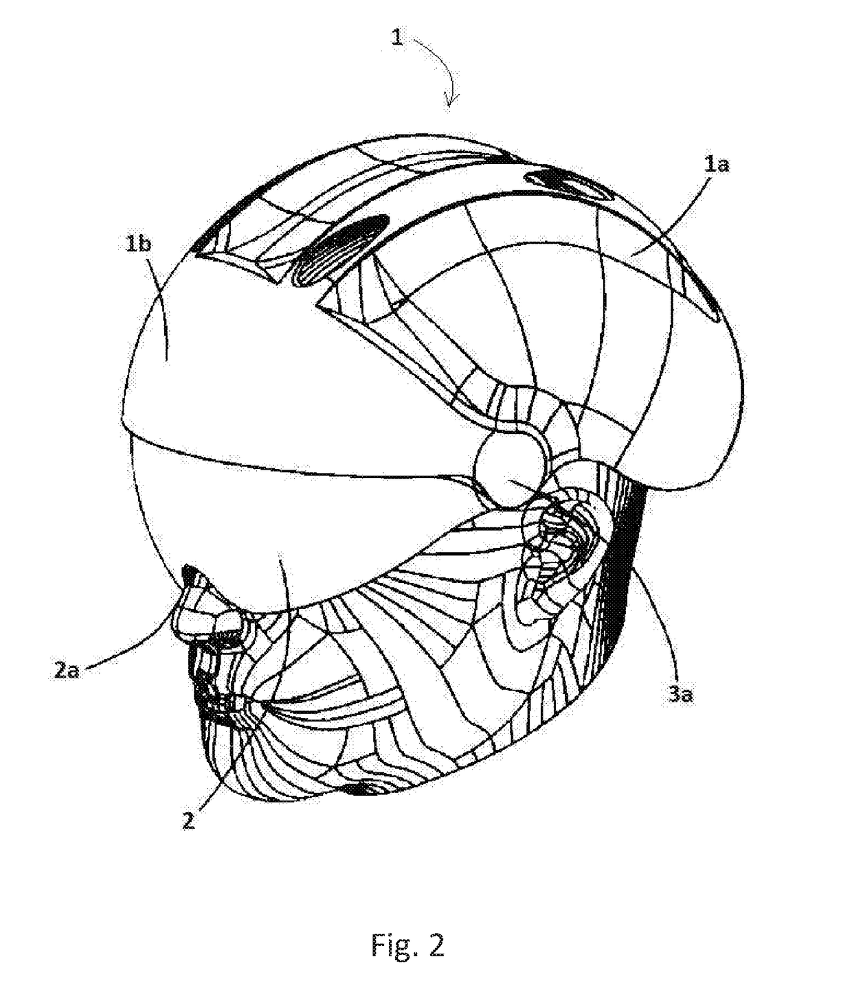
Helmet

a technology for helmets and helmet covers, applied in the field of helmets, can solve the problems of eye protection not being provided to a person, eye damage, eye damage, etc., and achieve the effect of improving the visibility of users

Active Publication Date: 2018-02-01
SMALLWOOD IOAN
View PDF15 Cites 12 Cited by
  • Summary
  • Abstract
  • Description
  • Claims
  • Application Information

AI Technical Summary

Benefits of technology

[0008]The present invention is derived from the realisation that there exists the need to provide a helmet that meets the required safety standards, which improves the visibility of a user and which includes a retractable visor which does not require the user to select the retracted state.
[0015]The helmet may further comprise a shield portion located at the forward region of the shell for providing a shielding effect to the surface of the visor when it is in the second position so as to protect the outer surface of the visor.
[0019]In use the users head may come into contact with the actuator and the resulting force applied thereto causes the actuator to move towards the inner surface of the shell thereby reducing the distance between the actuator and the inner surface of the shell.

Problems solved by technology

Whilst such a helmet is configured to protect the head of a person in situations involving simple, low speed falls, there is no protection afforded to a persons eyes.
The eyes are particularly vulnerable when a person is riding at speed, when it is raining or snowing or another adverse weather condition, or when parts from the road surface are lifted towards the face of the cyclist.
It is known for a cyclist to wear glasses so as to protect their eyes, however these are a separate and distinct elements that can be easily misplaced and are usually fragile and easily breakable.
Further, rain can get on the inside of the lens and can enter the cyclist eyes.
Whilst it is desirable to configure the visor in the stored state when it is not in use, the user may not always remember to do so and when the visor is down it can be knocked and marked.
These marks can be detrimental to the vision of the user.

Method used


Image

  • Helmet
  • Helmet
  • Helmet

Examples


second embodiment

[0112]In the invention the stabilising arms 25a, 25b are configured to cause disengagement between the pivotable part and the locking member 8. Therefore the arms 25a, 25b act as the actuator for the release mechanism enabling movement of the visor 2, for example the stabilising arms 25a, 25b can be rotated, for example outwards to actuate release of the ratchet system.

third embodiment

[0113]In the invention as shown in FIG. 9, a rear strap 26 may be implemented as the actuator instead of the lever 18 to actuate the automated movement of the visor 2. The same principle would apply, whereby on insertion of the users head in the helmet, the strap would be moved towards the interior of the shell 1a, this time rearwardly of the users head, and would be mechanically linked to the pivotable member 7 so as to cause rotation of the pivotable member 7 and to mechanically communicate this rotation to the visor via the lockable member 8 thereby causing the visor 2 to be moved in front of the user eyes. Similarly, on removal of the helmet, the rear strap 26 would move away from the inner surface of the shell 1a and the pivotable member 7 would return to its original pivot position and the visor 2 would automatically move towards the stored state.

[0114]The time taken for the visor 2 to move from the first position to the second position is adjustable, therefore the speed of mo...


PUM


Abstract

The invention relates to a helmet, a method of manufacturing a helmet and a visor for a helmet. The helmet comprises a rigid shell dimensioned to receive the head of a wearer; a visor moveably attached to the shell and configurable between a first position in which the visor extends from a forward region of the shell and a second position in which the visor is substantially retracted with respect to the forward region of the shell, wherein in use actuation of the movement of the visor between the first position and the second position is automated on removal of the helmet from the head of a user.

Description

PRIORITY CLAIM[0001]This application claims priority to Great Britain application No. 1613127.8, filed Jul. 29, 2016.FIELD OF THE INVENTION[0002]This invention relates to a helmet, in particular a bicycle helmet with a retractable visor.BACKGROUND[0003]It is known for cyclists to wear a bicycle helmet as a protective measure, for instance a helmet may substantially reduce the incidence and severity of head injuries in the case of an accident. The helmet attenuates impact to the head of the user. It is important that the helmets are lightweight whilst providing the correct standard of protection. It is also important that a helmet does not obstruct the view of the user otherwise the helmet itself may be the cause of an accident. Therefore, known helmets are designed to minimise the interference with peripheral vision. Typical helmets comprise an outer shell and a liner formed of an impact absorbing element, for example a foamed polymer lines such as expanded polystyrene (EPS). The ou...

Claims


Application Information

Patent Timeline
Patent Type & Authority Applications(United States)
IPC IPC(8): A42B3/22A42B3/12
CPCA42B3/223A42B3/12A42B3/222A42B3/0466A42B3/163A42B3/224
Inventor SMALLWOOD, IOAN
Owner SMALLWOOD IOAN
Why Eureka
Try Eureka