Diaphragm entry for posterior surgical access

a technology for a diaphragm and a posterior section, which is applied in the field of minimally invasive surgery, can solve the problems of unfavorable patient access to unfavorable patient hemodynamics, and inability to easily see the anterior surface of the heart or other organs, and achieve the effect of sufficient column strength

Active Publication Date: 2018-02-01
ATRICURE
View PDF2 Cites 2 Cited by
  • Summary
  • Abstract
  • Description
  • Claims
  • Application Information

AI Technical Summary

Benefits of technology

The devices described in this patent allow for posterior surgical access to organs within the thoracic cavity. The devices include an elongate member with at least one working channel for inserting between organs, an expandable member to create a temporary cavity around the opening, and a rail-member to assist in positioning and manipulation of tissue structures within the body. The elongate member can be tapered to make manipulation easier, and there may be additional access ports for placement and visualization of the coagulation patterns. The patent also mentions the use of a guide wire and the avoidance of dissection of pericardial reflections to create a desired coagulation lesion. Overall, the patent provides tools to improve the surgical procedure and minimize damage to the patient.

Problems solved by technology

With a median sternotomy, although the heart can be lifted and manipulated by hand, the posterior surface of the heart or other organs is still not readily visible unless the heart is significantly rotated or lifted.
However, significant rotation or lifting of the heart may cause undesirable hemodynamic issues during beating heart procedures.
Any coughing or dramatic movement is extremely painful to the patient because the chest moves.
Clearly, rehabilitation after the medial sternotomy requires a significant amount of time.
Much of the pain during the rehabilitation process is due to the cutting of the muscles.
A thoracotomy provides limited access and visualization to the heart unless endoscopes are used.
Yet, even the use of endoscopes provides limited access to the posterior regions of the heart and lungs because these organs cannot be lifted or rotated easily.
However, this technique does not provide ready access or visualization of posterior regions of the heart or other organs.
Accordingly, subxyphoid techniques are often limited to procedures that target the anterior or apical ventricular regions.
The conventional surgical techniques discussed do not provide the medical practitioner with sufficient visibility of anatomic structures within the thoracic cavity.
For example, these procedures do not provide sufficient visibility for anatomic structures located along or adjacent to the posterior surface of the heart or lungs.
Accordingly, surgical practitioners may be hesitant to treat tissues located along or adjacent to the posterior heart or lungs during less invasive procedures, given the inability to visually observe the target area.
As such, minimally invasive cardiothoracic surgery has been limited to those anatomic structures located along the anterior surface of the heart.
Atrial fibrillation surgery is just one example of a surgical procedure that, while it relies on the surgical techniques discussed above, the procedure also suffers from shortcomings due to a lack of access to organs within the thoracic cavity.
Atrial fibrillation surgery involving radiofrequency, DC, microwave, ultrasound, laser or other modes of thermal ablation of atrial tissue has a limitation where tissue contact throughout the length of the electrode(s) is / are not consistent.
Such inconsistent electrode contact causes variability in the transmission of energy throughout the target length of ablated / coagulated tissue.
This inconsistency also produces undesirable gaps of viable tissue that promote propagation of wavelets that sustain atrial fibrillation, or produce atrial flutter, atrial tachycardia, or other arrhythmia substrate.
As discussed above, conventional means of surgical access are not optimal to access the posterior surfaces.
Another factor that contributes to the inability of existing thermal ablation probes to create complete curvilinear, transmural lesions is the presence of convective cooling on the opposite surface of the atrium.
Another deficiency of current approaches is the inability to direct the coagulation to precise regions of soft tissue while avoiding underlying or nearby tissue structures.
In a third example, the esophagus resides along the posterior left atrium between the left and right pulmonary veins; unanticipated heating of the esophagus during atrial fibrillation treatment can produce esophageal fistulas which can be associated with high morbidity and mortality rates.
Conventional approaches cannot selectively ablate the desired soft tissue structures while isolating other tissue structures that are intended to be preserved from targeted regions.

Method used


Image

  • Diaphragm entry for posterior surgical access
  • Diaphragm entry for posterior surgical access
  • Diaphragm entry for posterior surgical access

Examples


Embodiment Construction

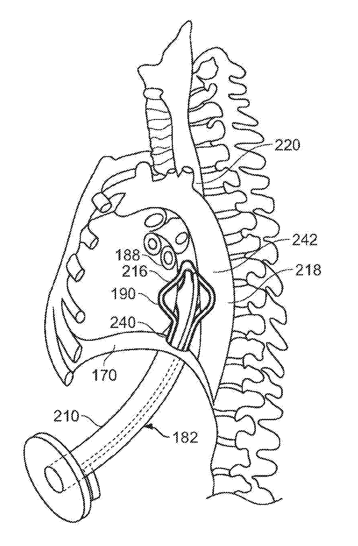
[0073]Methods and devices described herein provide for improved manipulation of organs and / or instruments in the thoracic cavity. The methods and devices may allow for direct visualization along the posterior region of the heart and other anatomic structures not attainable with conventional thoracic approaches. In one instance, the access devices described herein can be combined with a rail-member for accurate positioning of treatment devices over tissue.

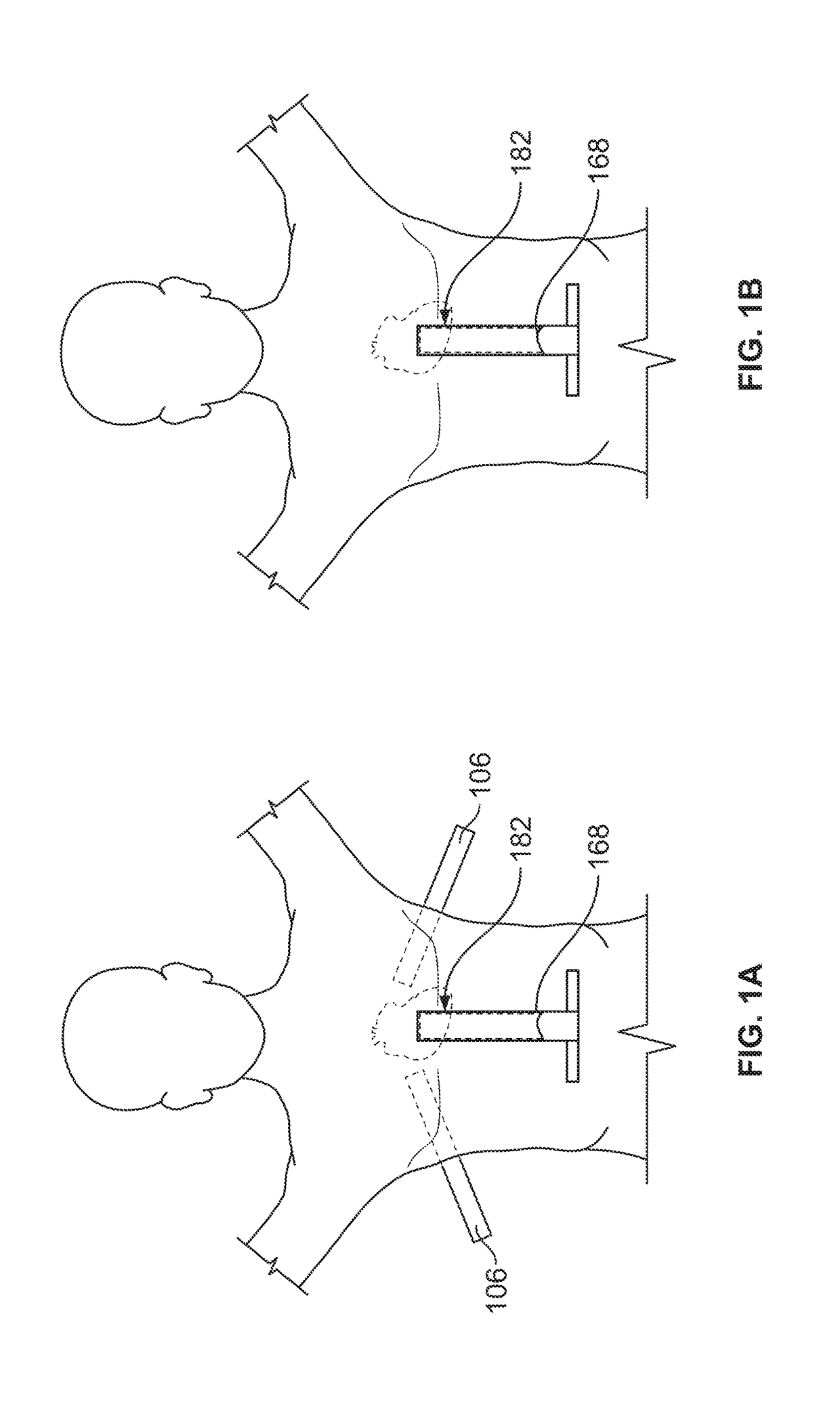
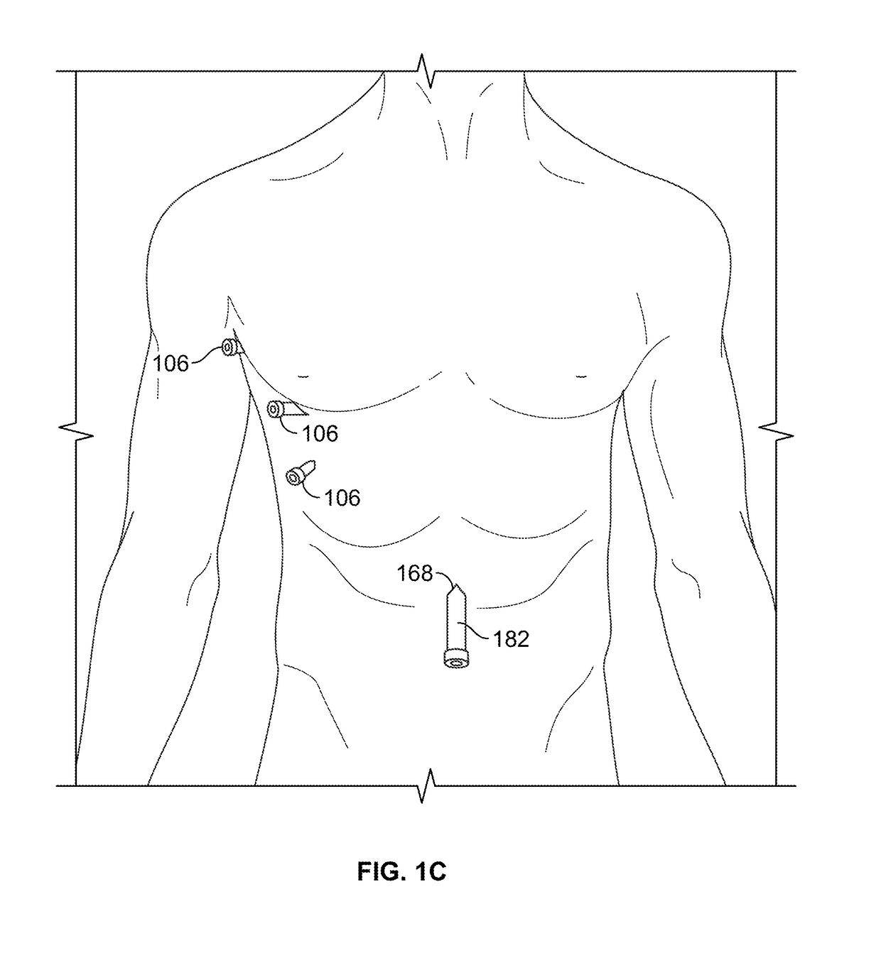
[0074]Furthermore, the methods and devices described herein may be used in conjunction with, or as an alternative to the conventional approaches described herein. In general, the surgical approaches and procedures described herein rely on entry through the diaphragm of a patient to access a posterior region of that patient (the procedure hereafter referred to as “Diaphragm Entry for Posterior Access” or simply “DEPA”). The DEPA procedure may also be referred as VAPS (Video-Assisted Pericardiac Surgery) or TAPS (Trans-Abdominal Peric...


PUM


Abstract

Methods and devices described herein facilitate improved treatment of body organs.

Description

[0001]This application is a continuation of U.S. patent application Ser. No. 11 / 737,493 filed Apr. 19, 2007, which is a continuation-in-part of U.S. patent application Ser. No. 11 / 408,315, entitled, “Diaphragm Entry for Posterior Surgical Access”, filed Apr. 21, 2006 (now U.S. Pat. No. 9,561,044 issued Feb. 7, 2017), which is a non-provisional of U.S. Provisional Application No. 60 / 726,342 filed Oct. 12, 2005. U.S. patent application Ser. No. 11 / 737,493 is also a continuation-in-part of U.S. patent application Ser. No. 11 / 558,417 entitled, “Diaphragm Entry for Posterior Surgical Access”, filed Nov. 9, 2006 (now U.S. Pat. No. 8,721,597 issued May 13, 2014), and U.S. patent application Ser. No. 11 / 558,419 “Diaphragm Entry for Posterior Surgical Access”, filed Nov. 9, 2006 (now U.S. Pat. No. 8,211,011 issued Jul. 3, 2012), entitled. Each of the above filings is hereby incorporated by reference in their entireties.BACKGROUND OF THE INVENTIONField of the Inventions[0002]Embodiments of th...

Claims


Application Information

Patent Timeline
Patent Type & Authority Applications(United States)
IPC IPC(8): A61B17/34A61B17/02A61B17/00A61B17/12A61B17/29A61B17/30A61B17/32A61B18/00
CPCA61B17/3423A61B2017/3419A61B2018/00291A61B2017/3486A61B2017/3445A61B2017/308A61B17/0218A61B2017/0243A61B2017/00243A61B17/3421A61B17/320016A61B17/12A61B2017/2905
Inventor WHAYNE, JAMES G.FLEISCHMAN, SIDNEY D.SCHLIEMAN, REBECCAROGERS, EARL W.
Owner ATRICURE
Why Eureka
Try Eureka