Wrench with a Ratchet Mechanism

a ratchet mechanism and wrench technology, applied in the field of hand tools, can solve the problem that the user may only be able to rotate the driving member, and achieve the effect of improving work efficiency, facilitating selection of driving mechanisms, and stable seating of components

Inactive Publication Date: 2018-02-01
STANLEY CHIRO INT
View PDF7 Cites 6 Cited by
  • Summary
  • Abstract
  • Description
  • Claims
  • Application Information

AI Technical Summary

Benefits of technology

[0007]The present disclosure describes a ratchet mechanism that provides a more stable seating of the components, so that the mechanism is

Problems solved by technology

Consequently, in some cases a user may only be able to rotate the driving memb

Method used


Image

  • Wrench with a Ratchet Mechanism
  • Wrench with a Ratchet Mechanism
  • Wrench with a Ratchet Mechanism

Examples


Embodiment Construction

[0031]The following is a description of the possible embodiments of the present invention by way of example only, and is not intended to limit the scope of the present invention.

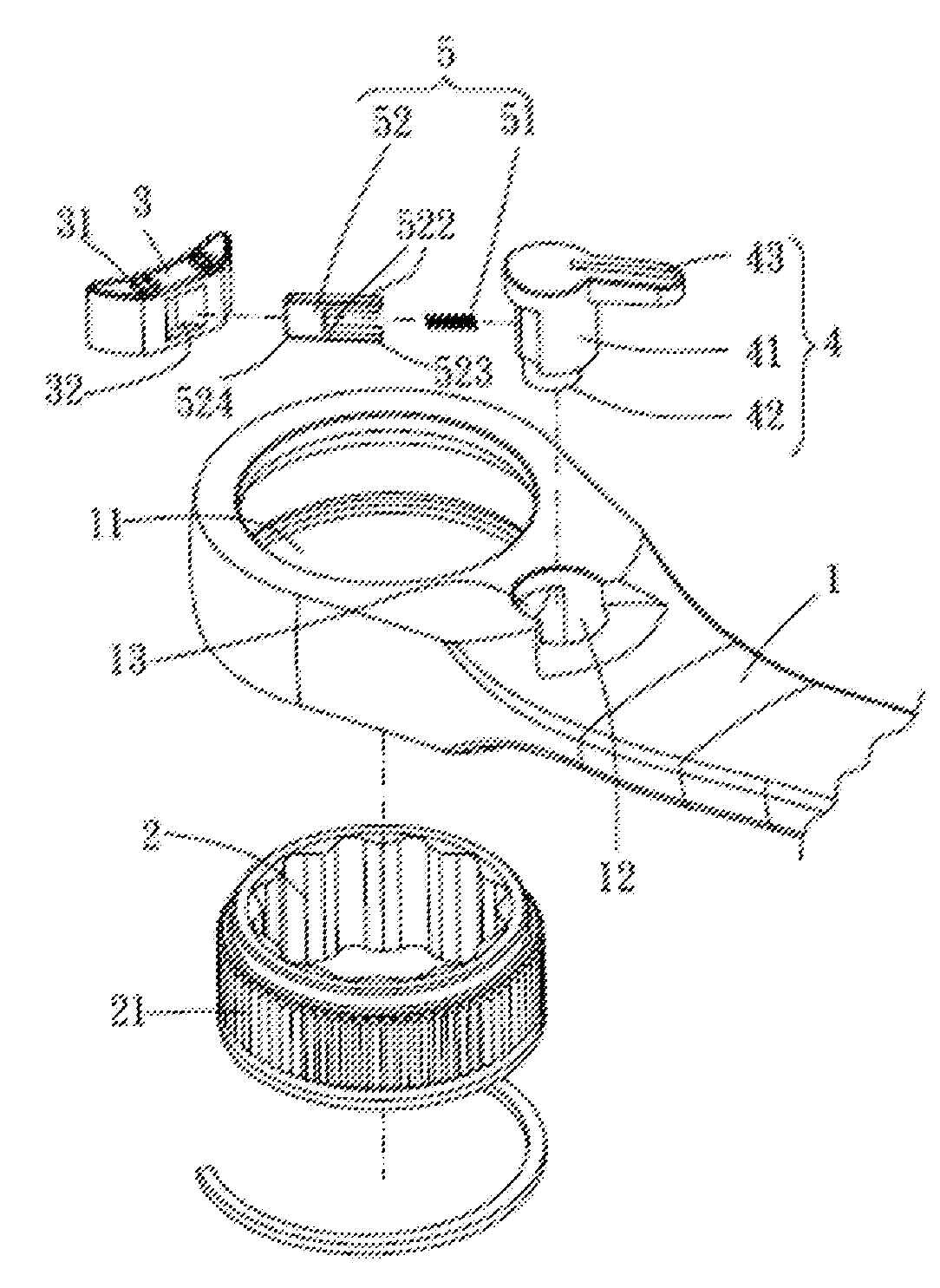
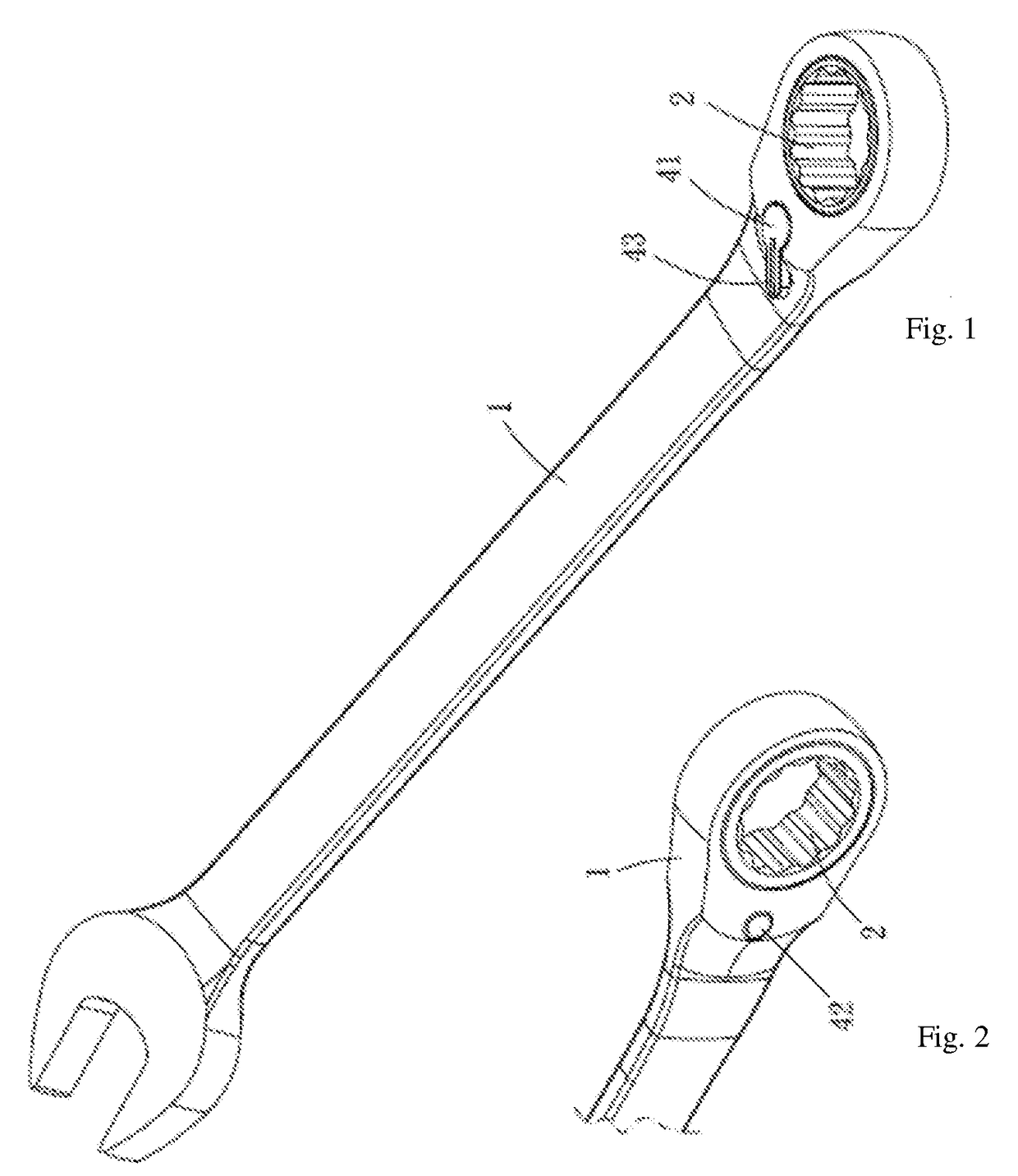
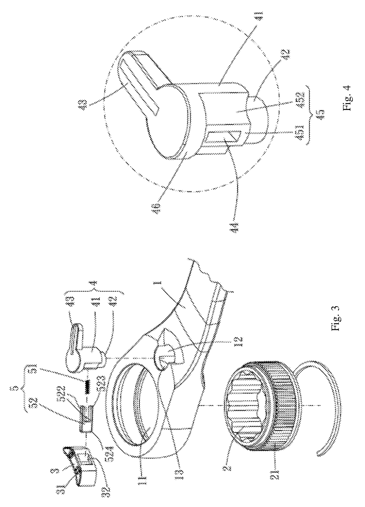
[0032]Please refer to FIGS. 1 to 6, which depict one embodiment of the present invention. The ratchet wrench of the present invention comprises a body 1, a driving member 2, a stopping member 3, a switching member 4, and an elastic abutting assembly 5.

[0033]The body 1 is provided with a first chamber 11, a second chamber 12 adjacent to the first chamber 11, and a third chamber 13 that communicates with the first chamber 11 and the second chamber 12, one of the two ends of the second chamber 12 forming a large diameter section 121, and the other end forming a small diameter section 122.

[0034]The driving member 2 is rotatably provided in the first chamber 11 and is provided with a first pawl portion 21 along the outer peripheral surface. In the present embodiment, the first pawl portion 21 may have, for exampl...


PUM


Abstract

A hand tool or wrench with a ratcheting mechanism. The wrench includes a number of components such as an abutting block and a pawl for use in a bistable ratchet operation. The wrench includes a ratchet mechanism that provides stable seating of the components, so that the mechanism is securely retained in a driving mode, as well as enabling a user to select a driving mechanism with ease so as to improve work efficiency.

Description

[0001]This patent application claims priority to TW application No. 105123822 filed 28 Jul. 2016 which is hereby incorporated by reference in its entirety.FIELD OF THE INVENTION[0002]The present invention relates to hand tools, and more particularly to a ratchet mechanism, for example for use in wrenches, screwdrivers, and the like.BACKGROUND TO THE INVENTION[0003]Rotational ratchet mechanisms are known. Common designs allow users to select a driving direction in which a torque may be transferred from, for example, a handle of the device to a driving member. Wrenches, screwdrivers and other tools may include a ratchet mechanism which allows a user to select a rotational direction in which torque can be applied to a screw, nut, bolt, etc. by rotating the handle in the corresponding direction. When the handle is rotated in the opposite direction, the mechanism operates as a ratchet, and does not transfer torque to the screw, nut, bolt etc.[0004]Typically, either rotational direction i...

Claims


Application Information

Patent Timeline
IPC IPC(8): B25B13/46B25B13/04
CPCB25B13/463B25B13/00B25B13/465B25B13/04B25B13/08B25B13/468
Inventor CHOU, HENRYCHAN, YI TUNG
Owner STANLEY CHIRO INT
Why Eureka
Try Eureka