
Corner-Based Longitudinal Speed Estimation

a longitudinal speed and estimation method technology, applied in the field of system and method for estimating longitudinal velocity of an object, can solve the problems of large oscillation and drift, low performance of combined slip maneuver, and estimation errors

Active Publication Date: 2018-02-01
GM GLOBAL TECH OPERATIONS LLC
View PDF0 Cites 19 Cited by
  • Summary
  • Abstract
  • Description
  • Claims
  • Application Information

AI Technical Summary

Benefits of technology

The present invention relates to a vehicle control system that can measure wheel speed and use a processor to determine the acceleration at the vehicle center of gravity and at the vehicle corner. This information can then be used by a controller to control the vehicle. The technical effect of this invention is that it provides a more accurate measure of the vehicle's acceleration and allows for better control of the vehicle's movements.

Problems solved by technology

These methods may result in estimation errors, large oscillations and drift for high-slip conditions, and low performance for the combined-slip maneuvers because of not using a bounded and stable tire force model.
Other methods utilize a tire model in the velocity estimation which also may be inaccurate as a result of unknown road friction and dependency to the tire parameters.
Tire forces can be measured at each corner, but their cost impact, calibration and maintenance are their major drawbacks to be used for production vehicles.
Provided that the longitudinal tire force calculation needs road friction, even accurate slip ratio information from the GPS will not provide forces at each corner.

Method used


Image

  • Corner-Based Longitudinal Speed Estimation
  • Corner-Based Longitudinal Speed Estimation
  • Corner-Based Longitudinal Speed Estimation

Examples


Embodiment Construction

[0012]The following detailed description is merely exemplary in nature and is not intended to limit the disclosure or the application and uses thereof. Furthermore, there is no intention to be bound by any theory presented in the preceding background or the following detailed description.

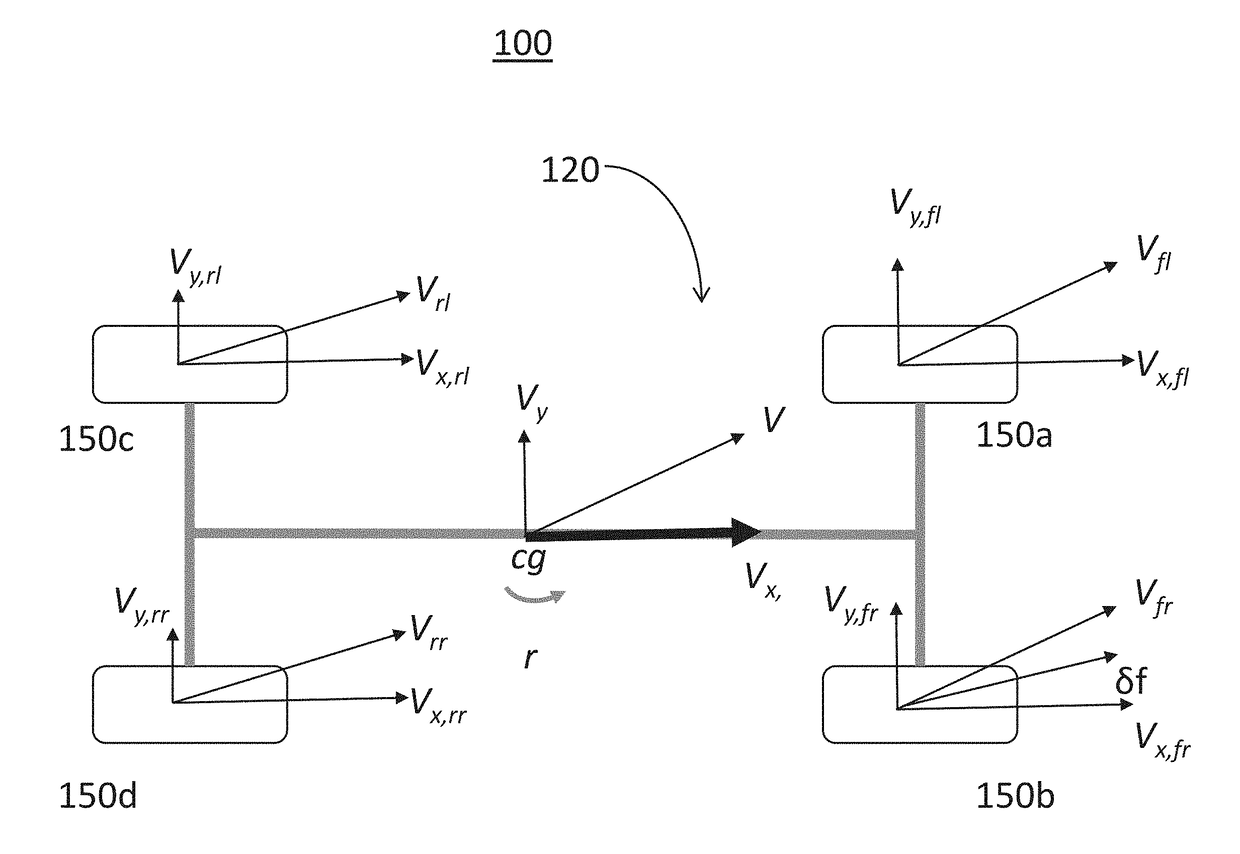
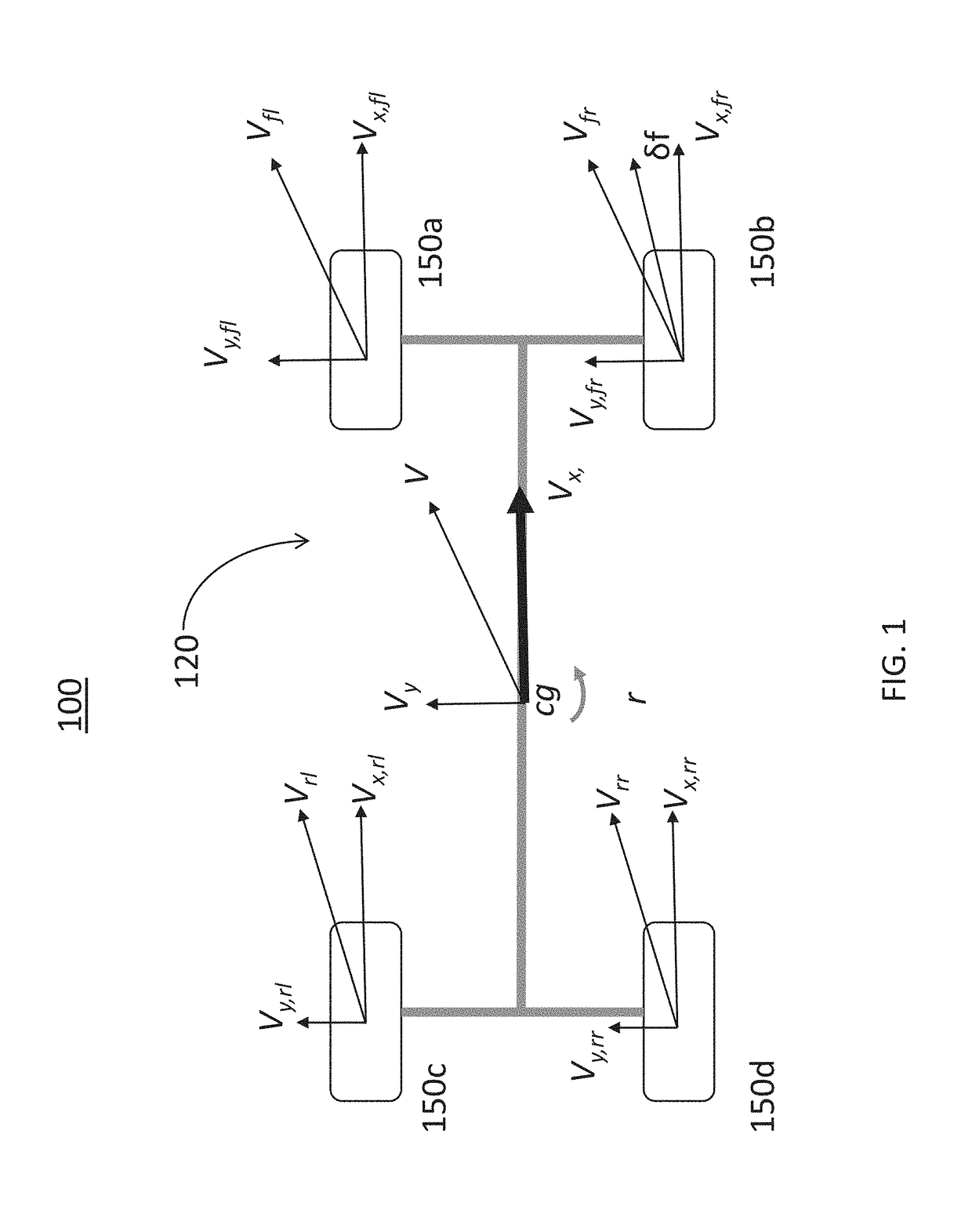
[0013]Referring now to the drawings, and more particularly to FIG. 1, a vehicle 120 experiencing a turning maneuver is illustrated. Longitudinal and lateral velocities at a center of gravity are indicated as vx and vy respectively. A yaw rate is denoted as r and a front steering angle is represented by δf. The center of gravity of the vehicle is denoted by cg. The longitudinal velocities of the four wheels are represented by vx,fl, vx,fr, vx,rl, and vx,rr (front-left, front-right rear-left, and rear-right respectively). Similarly, vy,fl, vy,fr, vy,rl, and vy,rr denote lateral velocities at the four wheels a left front wheel 150a, a front right wheel 150b, a left rear wheel 150c, and a right rear whe...


PUM


Abstract

A system and method for computationally estimating a directional velocity of a vehicle in real time under different configurations and road conditions for use in vehicle antilock braking, adaptive cruise control, and traction and stability control by correcting measured accelerations with respect to the estimated road angles. A time window is used to provide reliable mapped acceleration for the transient regions and maneuvers on gravel surfaces with high fluctuations in the acceleration measurement. Longitudinal and lateral accelerations are mapped from the vehicle's CG into the tire coordinates using the vehicle's geometry, lateral velocity, yaw rate, and the steering wheel angle to generate system matrices of the combined kinematic-force estimation structure.

Description

INTRODUCTIONField of the Invention[0001]The present invention generally relates to a system and method for estimating longitudinal velocity of an object. More particular, the invention relates to a system and method for computationally estimating longitudinal velocity of a vehicle in real time under different configurations and road conditions for use in vehicle antilock braking, adaptive cruise control, and traction and stability control.Background Information[0002]Accurate vehicle velocity estimation is crucial for reliable performance of the vehicle's traction and stability control systems. Longitudinal velocity and lateral velocity are vehicle dynamic variables used by vehicle control systems. Longitudinal speed is a vehicle dynamic variable used for example by adaptive cruise control systems and antilock braking systems. Lateral velocity is a vehicle dynamic variable used for stability control systems. Longitudinal and lateral velocity are generally estimated via wheel speed se...

Claims


Application Information

Patent Timeline
IPC IPC(8): B60W40/105B60W40/101B60W40/107B60W30/14B60T8/172G16Z99/00
CPCB60W40/105B60W30/14B60T8/172B60W40/107B60W40/101B60T8/1755G06F19/00B60L3/102B60W40/114B60L3/108B60W2520/28B60T2201/16B60T2250/04B60W30/02B60W40/109B60W2520/105B60W2520/125B60W40/10B60W2050/0052G16Z99/00
Inventor KASAIEZADEH MAHABADI, SEYEDALIREZAHASHEMI, EHSANKHAJEPOUR, AMIRCHEN, SHIH-KENLITKOUHI, BAKHTIAR B.
Owner GM GLOBAL TECH OPERATIONS LLC
Learn More