Method for operating a lift system

Active Publication Date: 2018-02-01
TK ELEVATOR INNOVATION & OPERATIONS GMBH
View PDF14 Cites 2 Cited by
  • Summary
  • Abstract
  • Description
  • Claims
  • Application Information

AI Technical Summary

Benefits of technology

[0029]On account of the fact that the drive remains active in this case and the car position is regulated at the corresponding setpoint car position or stop position, the adjustment can be carried out automatically and as quickly as possible. The adjustment can therefore be carried out with a maximum possible degree of adjustment accuracy.
[0030]In order to carry out the adjustment, the drive of the car therefore does not first have to be activated out of a deactivated mode. Furthermore, it is, in particular, not necessary for a switch-on cycle to first be carried out before the adjustment can be carried out. Therefore, no delay times with which individual steps of the switch-on cycle are associated have to be taken into consideration. Therefore, a delay time between identifying the non-levelness and the adjustment being carried out is considerably reduced.
[0031]As explained in the introductory part, the problem that arises in the case of switch-on cycles of conventional elevator systems is that a drive moment cannot be precisely set or is

Problems solved by technology

A change of this kind in the cable length during a stop can lead to the car not being level, in the case of which the position of the car in the elevator shaft relative to the stopping floor changes.
In the case of switch-on cycles of this kind, it has proven problematical to subject the drive moment to precise pilot control and setting before the service brakes are released.
Particularly in the case of a large change in load of the car over a short time period (for example when a large number of passengers leave and/or enter the car), the loading of the car cannot be precisely determined or at least is hard to precisely determine using a load measurement sensor.
Accordingly, the drive moment also cannot be precisely set or is at least har

Method used


Image

  • Method for operating a lift system
  • Method for operating a lift system
  • Method for operating a lift system

Examples


Example

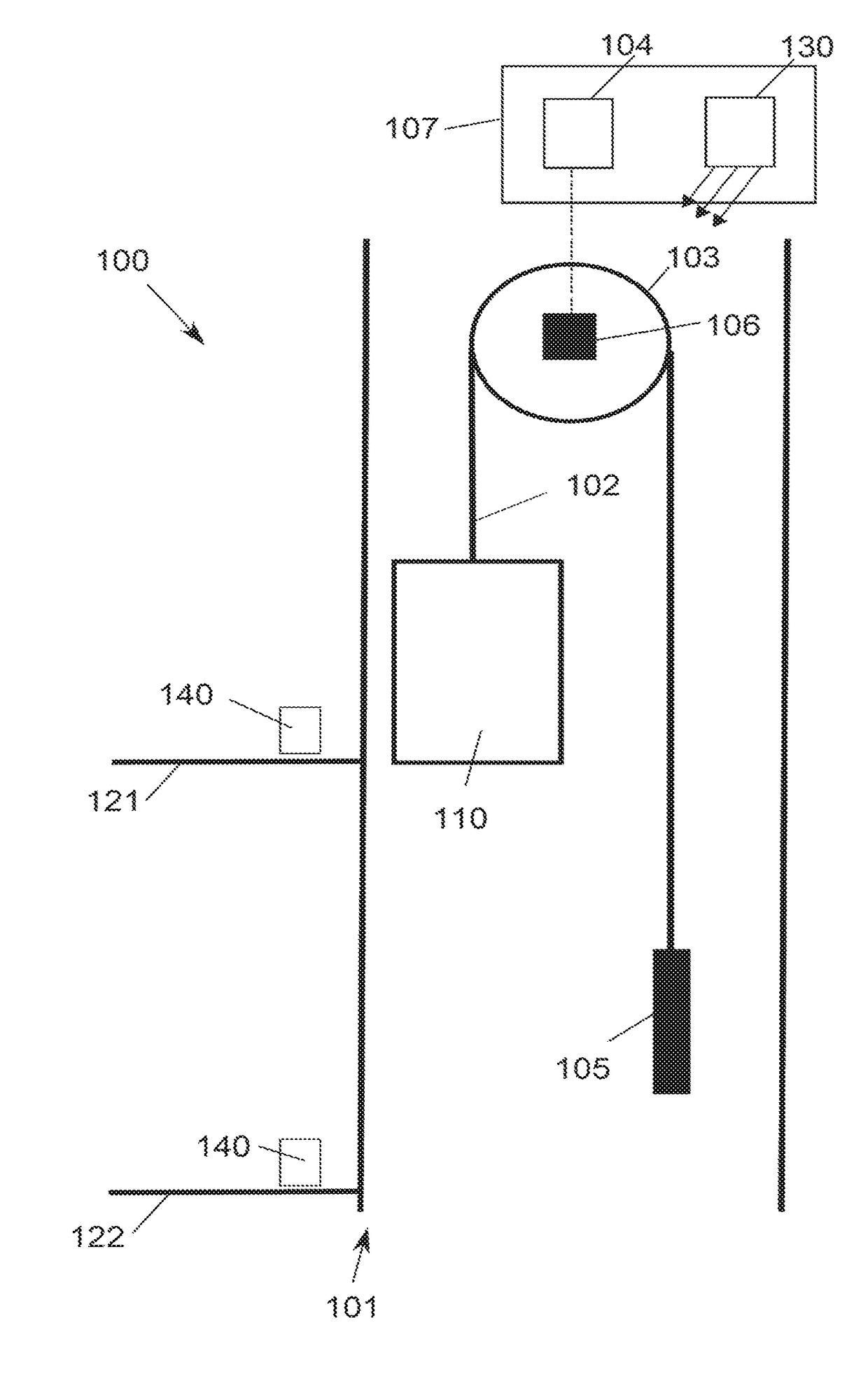
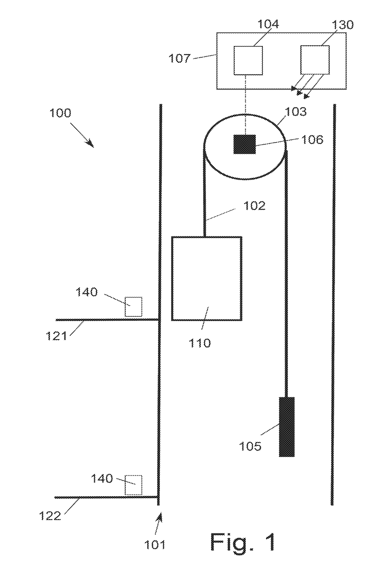
[0073]FIG. 1 schematically illustrates a preferred refinement of an elevator system according to the invention which is designated 100. A car 110 of the elevator system 100 can be moved in an elevator shaft 101. The car 110 is connected to a counterweight 105 by means of a suspension cable 102.

[0074]The car 110 is driven by a traction sheave drive 103 with motor 106. The traction sheave drive 103 is connected to a power supply system by means of an expedient connecting circuit. Said connecting circuit comprises two contactors 104 which are independent of one another, generally switching devices which are accommodated in the machine room 107.

[0075]The car 110 can be moved to several floors in the elevator shaft 101. Purely by way of example, FIG. 1 illustrates two floors 121 and 122. The elevator system comprises a destination selection controller. Input means 140, for example touchscreens or keypad input fields, are arranged at the different floors for a destination selection contro...


PUM


Abstract

A method for operating an elevator system with a car that moves in an elevator shaft may involve detecting an operating parameter related to a change in loading of the car, ascertaining whether a position of the car relative to a stopping floor needs to be adjusted based on the operating parameter, determining times at which the car is to be stopped and at which the adjustment is to be performed, stopping the car and blocking a flow of energy of a drive of the car and/or activating a service brake as the car is being stopped and/or while the car is stopped, and adjusting the position of the car if necessary. Further, whether the adjustment is necessary may be ascertained before the car is stopped.

Description

[0001]The present invention relates to a method for operating an elevator system comprising a car which is moved in an elevator shaft, wherein the car stops at a stopping floor, wherein the car is stopped at the stopping floor and a flow of energy is blocked and / or a service brake is activated in the process, wherein, in the case of the flow of energy being blocked, a flow of energy of a drive of the car is blocked, and wherein, in the case of the service brake being activated, a service brake is activated, and wherein, if required, a car position of the car is adjusted to the stopping floor, wherein the car position in the elevator shaft relative to the stopping floor is set during the course of the adjustment.PRIOR ART[0002]Strict safety requirements which are set, inter alia, by different standards apply to elevator systems. Corresponding safety guidelines are provided, in particular, by standard EN 81 (“Safety rules for the construction and installation of lifts”) from 1998 and ...

Claims


Application Information

Patent Timeline
IPC IPC(8): B66B1/40B66B5/02B66B5/00B66B9/00B66B1/44
CPCB66B1/40B66B1/44B66B5/0018B66B5/02B66B9/00
Inventor ALTENBURGER, BERND
Owner TK ELEVATOR INNOVATION & OPERATIONS GMBH
Why Eureka
Try Eureka