Motor drive device provided with disturbance load torque observer

Inactive Publication Date: 2009-04-16
FANUC LTD
View PDF4 Cites 5 Cited by
  • Summary
  • Abstract
  • Description
  • Claims
  • Application Information

AI Technical Summary

Benefits of technology

[0011]In other words, in the first aspect, the filtering means can cut the noise component, for example, the high frequency component, in the velocity detection value and / or torque command value. For this reason, it is possible to reduce the fluctuation in the disturbance load torque estimated value found by the disturbance load torque estimating means. Thus, even if raising the response of the disturbance torque estimating means, it is possible to suppress major variation in the disturbance load torque estimated value. As a result, it is possible to accurately judge abnormalities of the motor based on the disturbance load torque estimated value.
[0013]In other words, in the second aspect, by making the time constants of the two filtering means equal, the time delay can be made equal. For this reason, it is possible to further reduce the fluctuation of the disturbance load torque estimated value found by the disturbance load torque estimating means.

Problems solved by technology

If such a driven member strikes another object, movement or rotation of the driven member is obstructed or the transmission mechanism breaks down and as a result an excessive load is applied to the motor.
As a result, the motor breaks down or the driven member is damaged.
Furthermore, when the estimated disturbance torque exceeds the reference torque, it is judged that the motor has been subjected to an excessive load and the motor is stopped.
Furthermore, when it is judged that the rotational speed of the motor has exceeded a reference speed and that the disturbance torque is less than the reference torque, it is judged that an abnormality has occurred.
In such a case, it is not possible to accurately judge abnormalities of the motor.

Method used


Image

  • Motor drive device provided with disturbance load torque observer
  • Motor drive device provided with disturbance load torque observer
  • Motor drive device provided with disturbance load torque observer

Examples


Embodiment Construction

[0019]Below, embodiments of the present invention will be explained with reference to the attached drawings. In the following drawings, the same members are assigned the same reference numerals. To facilitate understanding, these drawings are suitably changed in scale.

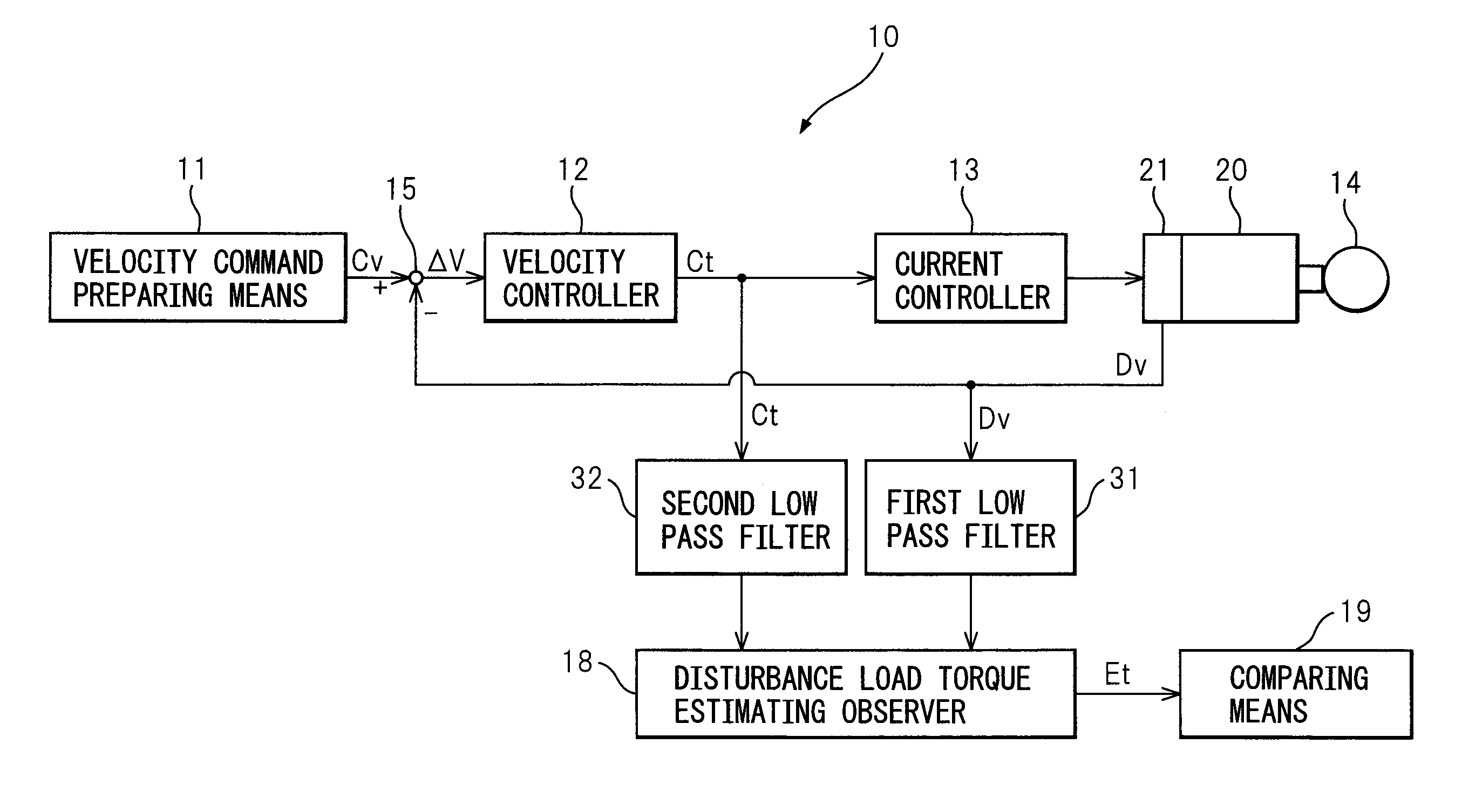
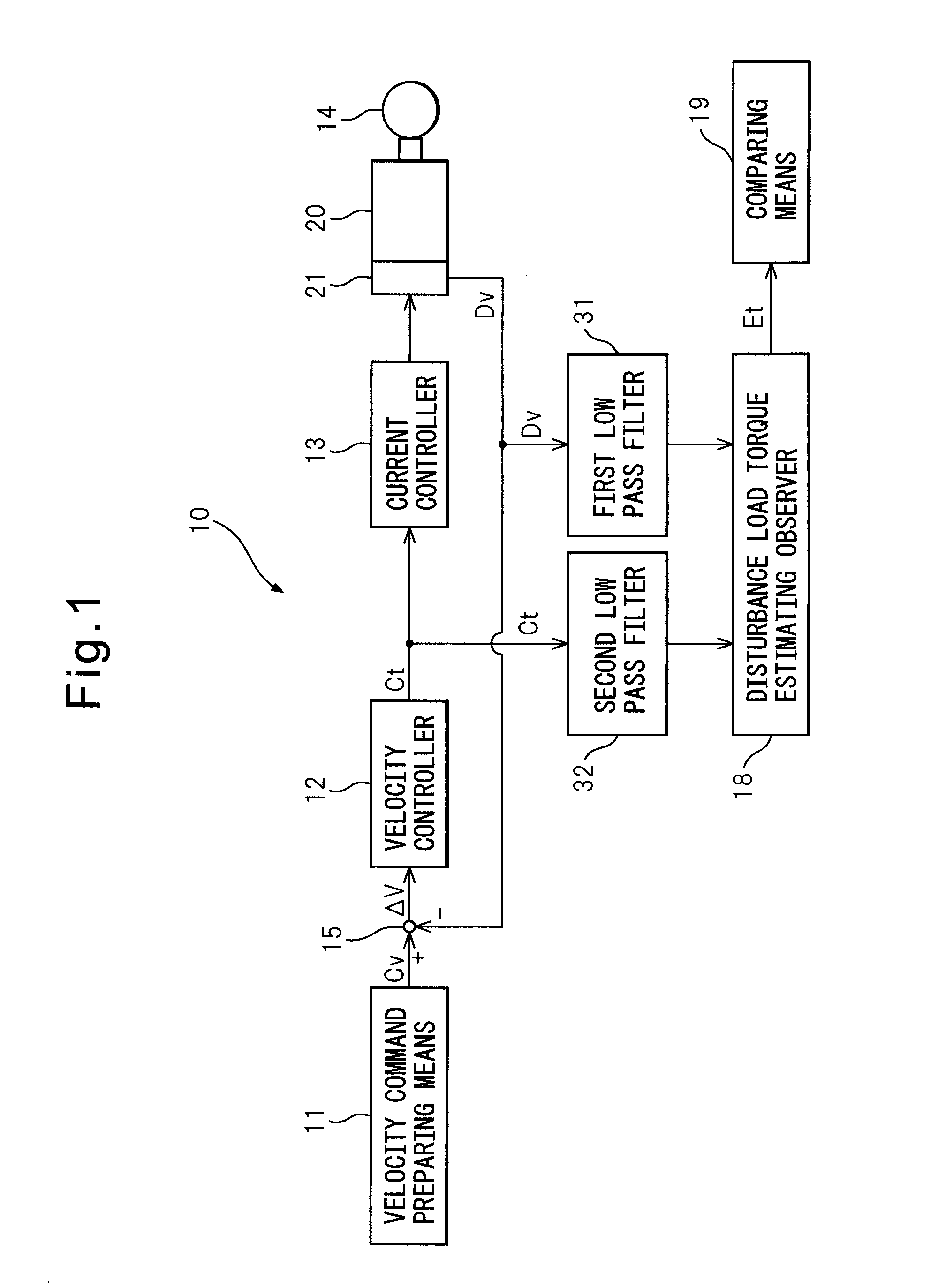
[0020]FIG. 1 is a block diagram showing the overall configuration of a motor drive device according to the present invention. The motor drive device 10 shown in FIG. 1 is connected to a motor 20 for driving the driven member 14. The motor 20 in the present invention need not be a servo motor and may also be a DC motor or another type of motor. Further, the motor 20 is provided with a velocity detecting means for detecting the rotational speed of the motor, for example, an encoder 21.

[0021]The driven member 14 is coupled through a ball-screw mechanism or other transmission mechanism (not shown) to the shaft of the motor 20 where it is moved or rotated by the rotation of the shaft of the motor 20. The driven member 14 is...


PUM


Abstract

A motor drive device (10) including a velocity command preparing means for preparing a velocity command value of a motor (20), a velocity detecting means (21) for detecting a velocity of the motor, a torque command value preparing means (12) for preparing a torque command value of a torque applied to the motor based on the velocity command value and a velocity detection value, and a disturbance load torque estimating means (18) for estimating a disturbance load torque applied to the motor based on a velocity detection value detected by the velocity detecting means and a torque command value prepared by the torque command preparing means, which motor drive device (10) is further provided with at least one of a first filtering means (31) for removing a noise component in the velocity detection value and supplying the velocity detection value to the disturbance load torque estimating means and a second filtering means (32) for removing a noise component in the torque command value and supplying the torque command value to the disturbance load torque estimating means, whereby fluctuation in the torque estimated value is suppressed even if raising the response of the disturbance load torque estimating means.

Description

BACKGROUND OF THE INVENTION[0001]1. Field of the Invention[0002]The present invention relates to a motor drive device for driving a motor used for a spindle or feed shaft of a machine tool or industrial machine or a motor provided at a robot arm, more particularly relates to a motor drive device provided with a disturbance load torque observer.[0003]2. Description of the Related Art[0004]In a machine tool, robot, industrial machine, etc., in general its spindle, feed shaft, arm, or other driven member is coupled through a ball-screw mechanism or other transmission mechanism to a shaft of a motor and is driven by the motor.[0005]If such a driven member strikes another object, movement or rotation of the driven member is obstructed or the transmission mechanism breaks down and as a result an excessive load is applied to the motor. As a result, the motor breaks down or the driven member is damaged.[0006]To solve this problem, in Japanese Unexamined Patent Publication No. 6-82346, the d...

Claims


Application Information

Patent Timeline
IPC IPC(8): H02P7/00
CPCH02P23/0036H02P23/0004
Inventor IWASHITA, YASUSUKEOKITA, TADASHITEZUKA, JUNICHIYAMAMOTO, KENTA
Owner FANUC LTD
Why Eureka
Try Eureka