Device for the individual adjustment of a plurality of variable-pitch radial stator vanes in a turbomachine

Active Publication Date: 2018-02-01
SN DETUDE & DE CONSTR DE MOTEURS DAVIATION S N E C M A
View PDF25 Cites 3 Cited by
  • Summary
  • Abstract
  • Description
  • Claims
  • Application Information

AI Technical Summary

Benefits of technology

[0037]Advantageously, such a turbine engine does not comprise stator vanes mounted in the secondary duct downstream of the movable fan. The air flow deflected by the movable fan is axially straightened and does not require the p

Problems solved by technology

However, the devices for adjusting the variable-pitch of vanes that are already commonly present in turbine engines only allow a uniform variation of the pitch of the vanes.
However, they do not allow the pitch of the vanes to be dynamically adj

Method used


Image

  • Device for the individual adjustment of a plurality of variable-pitch radial stator vanes in a turbomachine
  • Device for the individual adjustment of a plurality of variable-pitch radial stator vanes in a turbomachine
  • Device for the individual adjustment of a plurality of variable-pitch radial stator vanes in a turbomachine

Examples


first embodiment

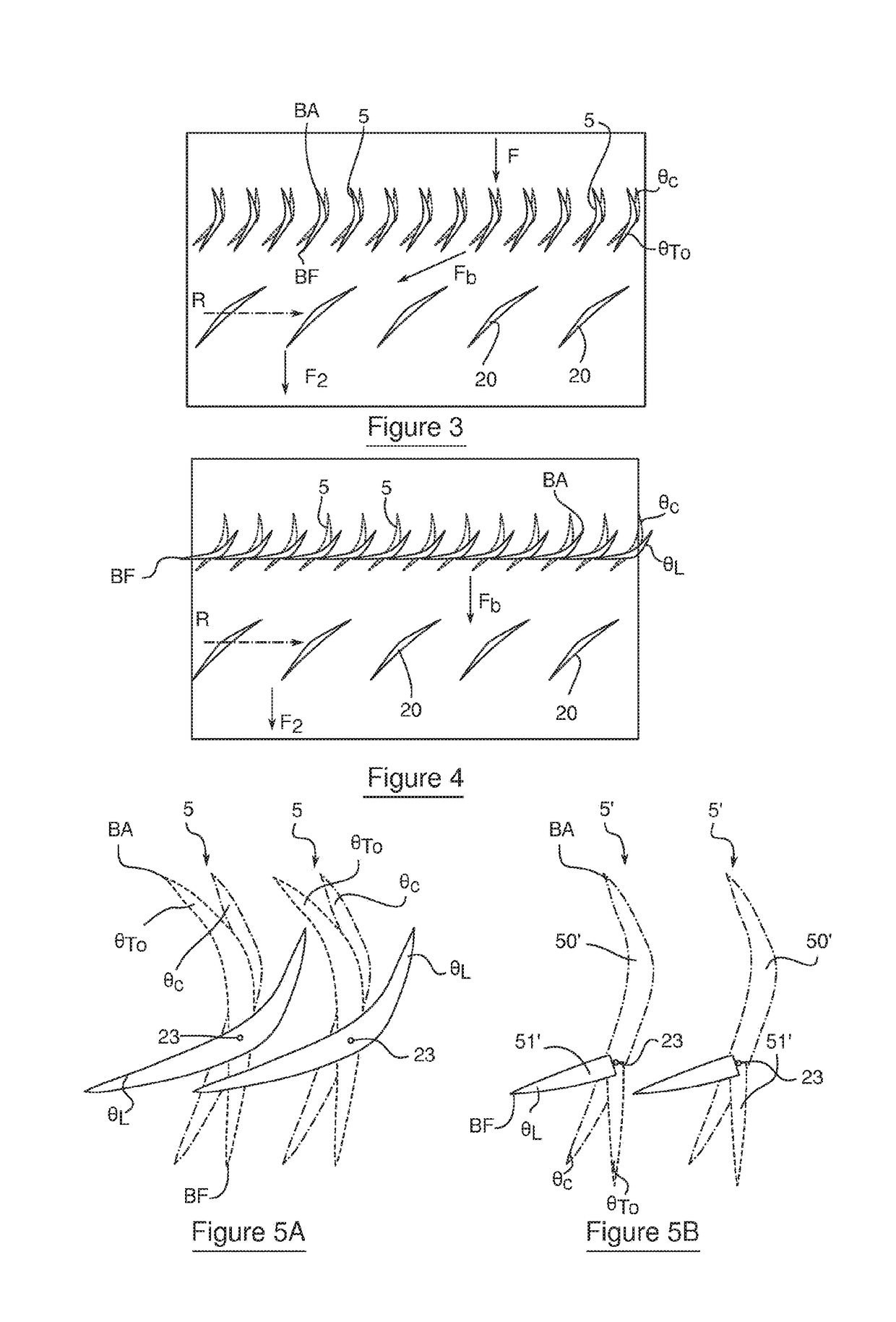
[0073]According to the variable-pitch stator vanes, each radial stator vane 5 comprises a one-piece movable body rotating about a radial pitch shaft 23 (FIG. 5A). Thus, depending on the operating state of the turbine engine 1, the entire radial stator vane 5 orients about the pitch shaft 23 along which it extends, so as to be set according to the pitch angles for cruising θc, for take-off θTO or when slowing down θL.

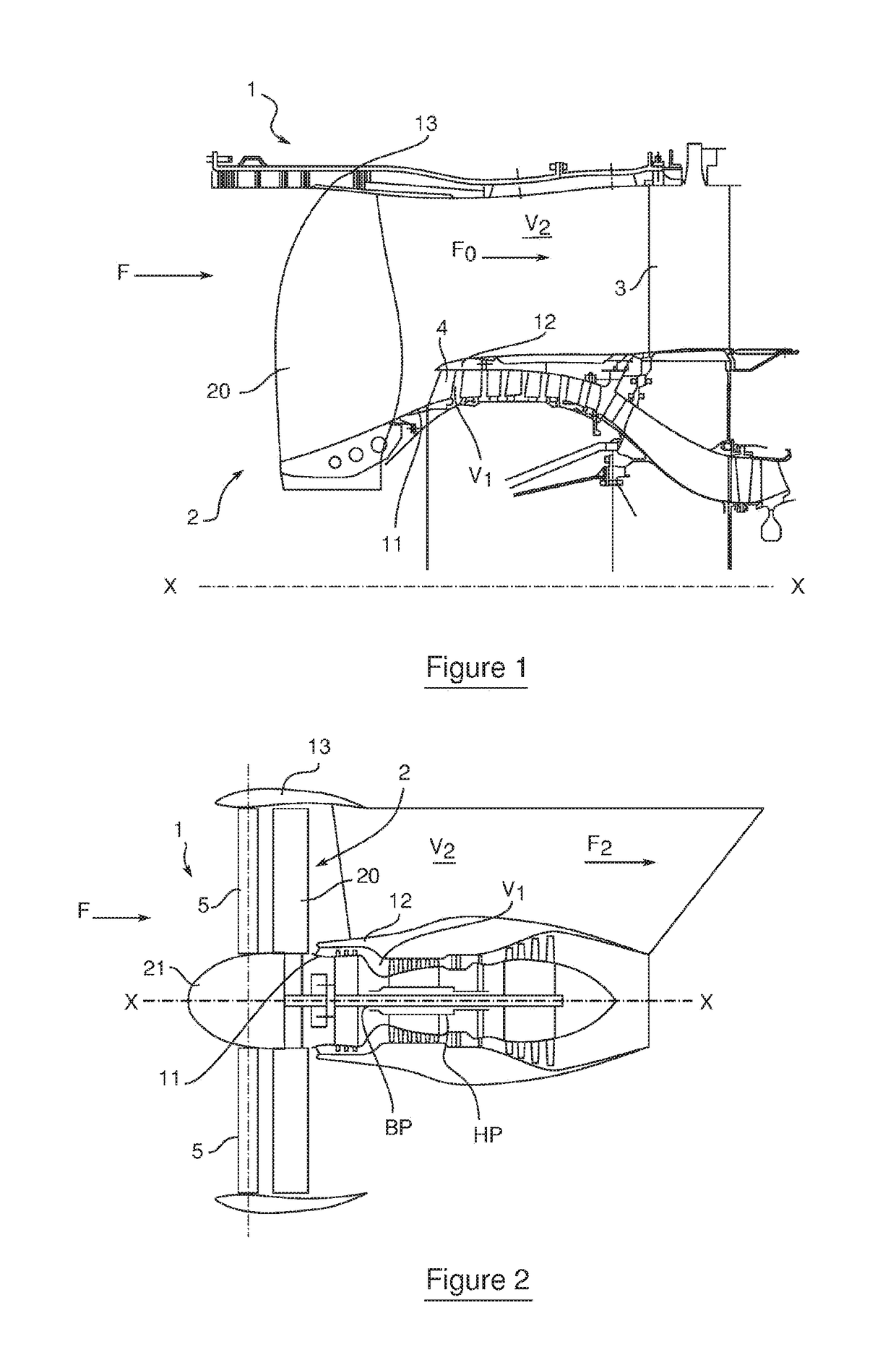
[0074]In this embodiment, with reference to FIG. 8 and FIG. 12, each radial stator vane 5 is thus mounted to rotate about a substantially radial pitch shaft 23 on a pivot means 22 rigidly connected to the outer casing 13, the pitch shaft 23 in this case opening out radially on the outside of the casing 13. The pitch shafts 23 of the radial vanes 5 are located in the same plane perpendicular to the longitudinal axis X-X of the turbine engine.

[0075]In this first embodiment, the means for individually adjusting the pitch of the radial stator vanes 5 are preferably located o...

second embodiment

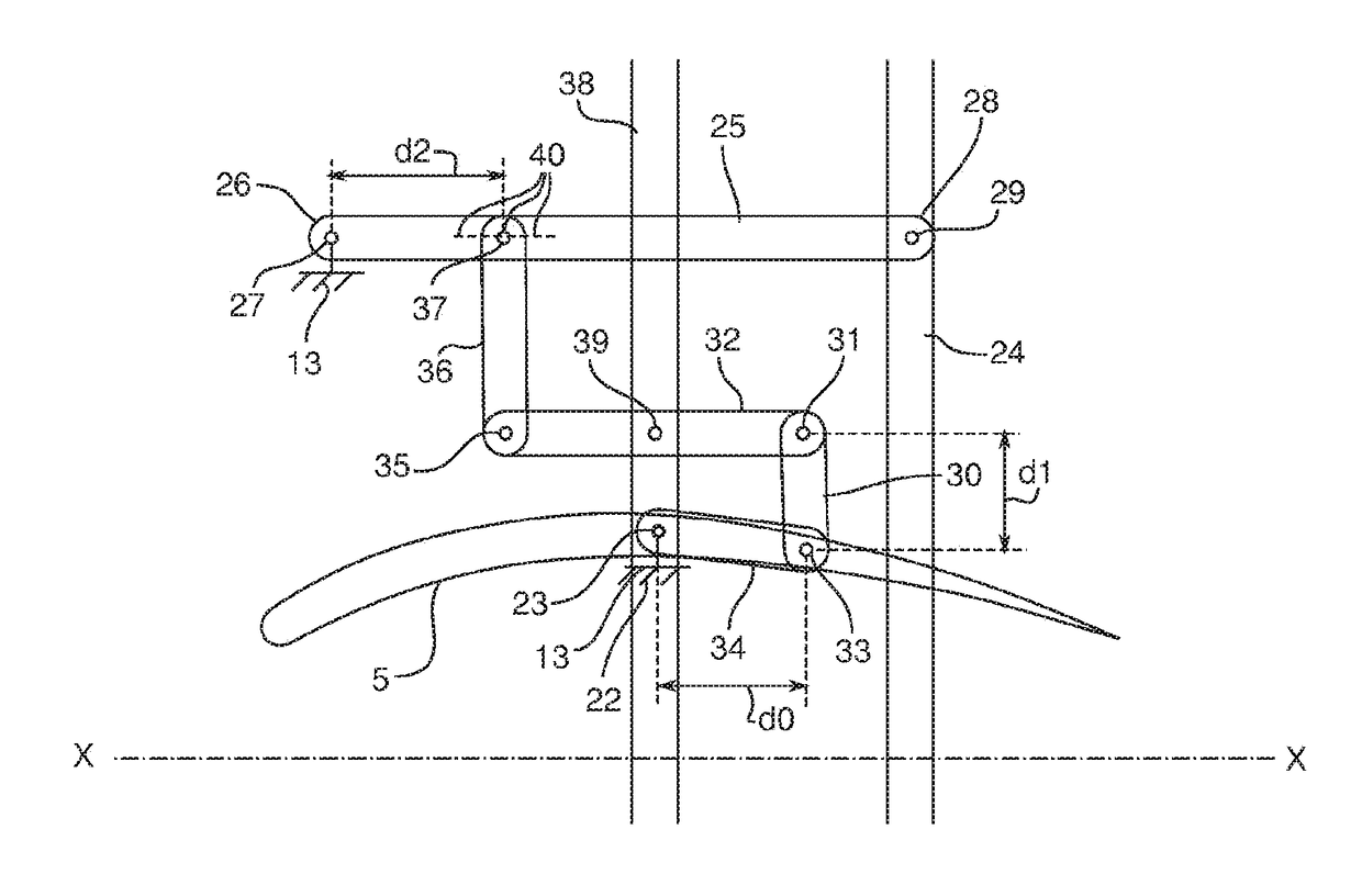
[0121]Furthermore, in this second embodiment, each radial vane 5 is connected to the control rings 40, 41 by a set of two connecting rods 42 and 43 articulated together about a first and single articulation shaft 44 for the set of substantially radial connecting rods.

[0122]The first connecting rod 42 is mounted, in the vicinity of one of its ends, to rotate about a first pivot shaft 45 that is substantially radial and is rigidly connected to the first control ring 24 and, in the vicinity of its other end, to rotate about a second pivot shaft 46 that is substantially radial and is rigidly connected to the second control ring 41.

[0123]For an average position of the two control rings 40, 41, the first connecting rod 42 in this case is substantially parallel to the longitudinal axis X-X and is offset by azimuth relative to the pitch shaft 23 of the vane 5.

[0124]The second connecting rod 43 is pivotally mounted, in the vicinity of its end that is opposite said first articulation shaft 44...


PUM


Abstract

A device for adjusting the pitch of at least one annular row of stator vanes for a turbine engine module. The device includes a first control ring mounted to rotate freely about an axis of the turbine engine. The device also includes connecting rods for connecting the first control ring to the vanes and a second control ring mounted to rotate freely about the axis. Each vane of the at least one row is simultaneously connected to the first and second control rings by a set of at least two connecting rods. The device is suitable for use as part of a module and is suitable for use in a turbine engine.

Description

GENERAL TECHNICAL FIELD AND PRIOR ART[0001]The present invention relates to the field of bypass turbine engines, particularly for aircraft, in which air flows circulate in an upstream to downstream direction. More specifically, it relates to means for adjusting the pitch of fixed vanes configured to deflect axial incident air into a duct of the turbine engine as a function of the flight conditions.[0002]Conventionally, with reference to FIG. 1, a turbine engine 1, as disclosed in patent application FR 2902142 by SNECMA, extends axially along an axis X-X and comprises an inner casing 11, an inter-duct casing 12 and an outer casing 13 so as to delimit a primary duct V1 between the inter-duct casing 12 and the inner casing 11 and a secondary duct V2 between the inter-duct casing 12 and the outer casing 13. In other words, the secondary duct V2 and the primary duct V1 are annular and are separated by the inter-duct casing 12.[0003]The turbine engine 1 comprises a rotary shaft, which ups...

Claims


Application Information

Patent Timeline
IPC IPC(8): F01D17/16
CPCF01D17/162F05D2250/42F05D2260/50F05D2230/72F05D2240/12F05D2220/323F05D2250/40Y02T50/60
Inventor BORDONI, NILS
Owner SN DETUDE & DE CONSTR DE MOTEURS DAVIATION S N E C M A
Why Eureka
Try Eureka