Methodology and application of acoustic touch detection

a technology of acoustic touch and detection method, applied in the field of touch sensing, can solve the problems of reducing the performance of capacitive or resistive touch sensing system, and unable to meet the needs of capacitive or resistive touch sensing, and achieve the effect of optimizing radio frequency performan

Active Publication Date: 2018-02-01
APPLE INC
View PDF1 Cites 70 Cited by
  • Summary
  • Abstract
  • Description
  • Claims
  • Application Information

AI Technical Summary

Benefits of technology

[0004]This relates to system architectures, apparatus and methods for acoustic touch detection (touch sensing) and exemplary applications of the system architectures, apparatus and methods. Position of an object touching a surface can be determined using time-of-flight (TOF) bounding box techniques, acoustic image reconstruction techniques, acoustic tomography techniques, attenuation of reflections from an array of barriers, or a two dimensional piezoelectric receiving array, for example. Acoustic touch sensing can utilize transducers, such as piezoelectric transducers, to transmit ultrasonic waves along a surface and / or through the thickness of an electronic device. As the wave propagates along the surface, one or more objects (e.g., finger, stylus, etc.) in contact with the surface can interact with the transmitted wave causing attenuation, redirection and / or reflection of at least a portion of the transmitted wave. Portions of the transmitted wave energy after interaction with the one or more objects can be measured to determine the touch location(s) of the one or more objects on the surface of the device. For example, one or more transducers (e.g., acoustic transducers) coupled to a surface of a device can be configured to transmit an acoustic wave along the surface and / or through the thickness of a device and can receive a portion of the wave reflected back when the acoustic wave encounters a finger touching the surface. The location of the object can be determined, for example, based on the amount of time elapsing between the transmission of the wave and the detection of the reflected wave. Acoustic touch sensing can be used instead of, or in conjunction with, other touch sensing techniques, such as resistive and / or capacitive touch sensing. In some examples, the acoustic touch sensing techniques described herein can be used on a metal housing surface of a device, which may be unsuitable for capacitive or resistive touch sensing due to interference (e.g., of the housing with the capacitive or resistive sensors housed in the metal housing). In some examples, the acoustic touch sensing techniques described herein can be used on a glass surface of a display or touch screen. In some examples, an acoustic touch sensing system can be configured to be insensitive to contact on the device surface by water, and thus acoustic touch sensing can be used for touch sensing in devices that are likely to become wet or fully submerged in water. The present disclosure also relates to methods and apparatus for optimizing radio frequency (RF) performance using acoustic touch sensing.

Problems solved by technology

Capacitive-type touch sensing system, however, can experience reduced performance due to floating objects (e.g., water droplets) in contact with the touch-sensitive surface.
In some examples, the acoustic touch sensing techniques described herein can be used on a metal housing surface of a device, which may be unsuitable for capacitive or resistive touch sensing due to interference (e.g., of the housing with the capacitive or resistive sensors housed in the metal housing).

Method used


Image

  • Methodology and application of acoustic touch detection
  • Methodology and application of acoustic touch detection
  • Methodology and application of acoustic touch detection

Examples


Embodiment Construction

[0037]In the following description of various examples, reference is made to the accompanying drawings which form a part hereof, and in which it is shown by way of illustration specific examples that can be practiced. It is to be understood that other examples can be used and structural changes can be made without departing from the scope of the various examples.

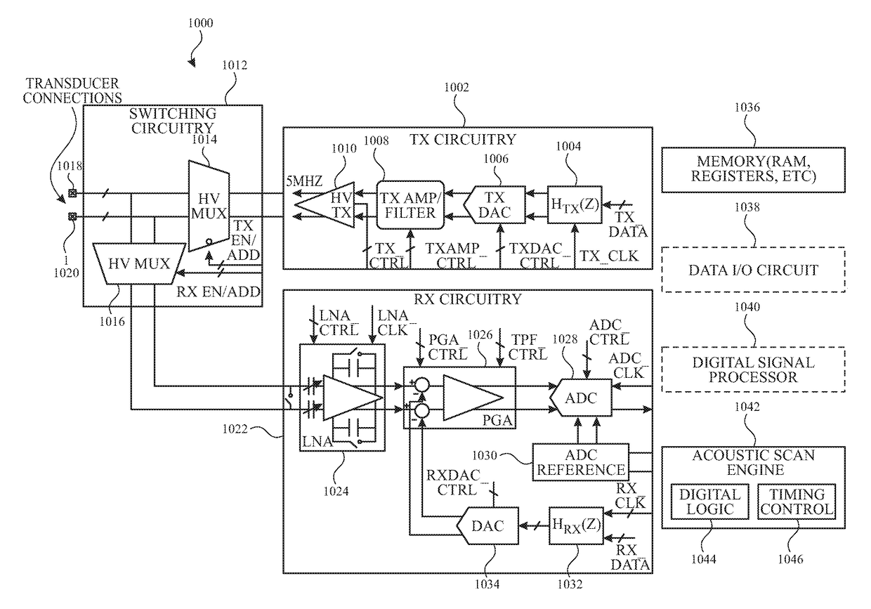
[0038]This relates to system architectures, apparatus and methods for acoustic touch detection (touch sensing) and exemplary applications of the system architectures, apparatus and methods. Position of an object touching a surface can be determined using time-of-flight (TOF) bounding box techniques, acoustic image reconstruction techniques, acoustic tomography techniques, attenuation of reflections from an array of barriers, or a two dimensional piezoelectric receiving array, for example. Acoustic touch sensing can utilize transducers, such as piezoelectric transducers, to transmit ultrasonic waves along a surface and / or thr...


PUM


Abstract

Acoustic touch detection (touch sensing) system architectures and methods can be used to detect an object touching a surface. Position of an object touching a surface can be determined using time-of-flight (TOF) bounding box techniques, or acoustic image reconstruction techniques, for example. Acoustic touch sensing can utilize transducers, such as piezoelectric transducers, to transmit ultrasonic waves along a surface and/or through the thickness of an electronic device. Location of the object can be determined, for example, based on the amount of time elapsing between the transmission of the wave and the detection of the reflected wave. An object in contact with the surface can interact with the transmitted wave causing attenuation, redirection and/or reflection of at least a portion of the transmitted wave. Portions of the transmitted wave energy after interaction with the object can be measured to determine the touch location of the object on the surface of the device.

Description

CROSS REFERENCE TO RELATED APPLICATIONS[0001]This application claims the benefit under 35 U.S.C. §119(e) of U.S. Provisional Patent Application No. 62 / 368,998, filed Jul. 29, 2016, and claims benefit to U.S. Provisional Patent Application No. 62 / 368,984, filed Jul. 29, 2016, and claims benefit to U.S. Provisional Patent Application No. 62 / 368,873, filed Jul. 29, 2016, and claims benefit to U.S. Provisional Patent Application No. 62 / 399,227, filed Sep. 23, 2016, and claims benefit to U.S. Provisional Patent Application No. 62 / 398,651, filed Sep. 23, 2016, the contents of which are incorporated by reference herein in their entireties for all purposes.FIELD OF THE DISCLOSURE[0002]This relates generally to touch sensing, and more particularly, to various methodologies and applications of acoustic touch detection.BACKGROUND OF THE DISCLOSURE[0003]Many types of input devices are presently available for performing operations in a computing system, such as buttons or keys, mice, trackballs,...

Claims


Application Information

Patent Timeline
Patent Type & Authority Applications(United States)
IPC IPC(8): G06F3/043H01Q1/00H01Q1/52H01Q7/00
CPCG06F3/0436H01Q7/005G06F2203/04106H01Q1/52G06F2203/04104H01Q1/002G06F1/3231G06F3/0433G06F1/1694G06F1/1698G06F1/325G06F1/3262G06F2200/1637G06F3/04186Y02D10/00
Inventor KING, BRIAN MICHAELYEKE YAZDANDOOST, MOHAMMADKHAJEH, EHSANTUCKER, AARON SCOTTGOZZINI, GIOVANNIYIP, MARCUSYOUSEFPOR, MARDUKEJADHAV, DIGVIJAYSEN, INDRANILNARANG, MOHITJIANG, YIMAJIDZADEH BAFAR, VAHIDKERAMAT, MANSOURXU, HAO
Owner APPLE INC
Why Eureka
Try Eureka