Substrate processing apparatus, lid cover and method of manufacturing semiconductor device

a technology of substrate processing and lid cover, which is applied in the direction of electrical apparatus, conveyor parts, electric discharge tubes, etc., can solve the problems of adversely affecting film formation

Active Publication Date: 2018-02-01
KOKUSA ELECTRIC CO LTD
View PDF2 Cites 298 Cited by
  • Summary
  • Abstract
  • Description
  • Claims
  • Application Information

AI Technical Summary

Benefits of technology

The invention described in this patent prevents unwanted substances from sticking to the bottom part of a container used for processing materials.

Problems solved by technology

The technical problem addressed in this patent relates to particle production during substrate processing with a vertical type substrate processing apparatus. These particles can negatively impact film formation and affect overall quality of the processed substrates.

Method used


Image

  • Substrate processing apparatus, lid cover and method of manufacturing semiconductor device
  • Substrate processing apparatus, lid cover and method of manufacturing semiconductor device
  • Substrate processing apparatus, lid cover and method of manufacturing semiconductor device

Examples


first modified example

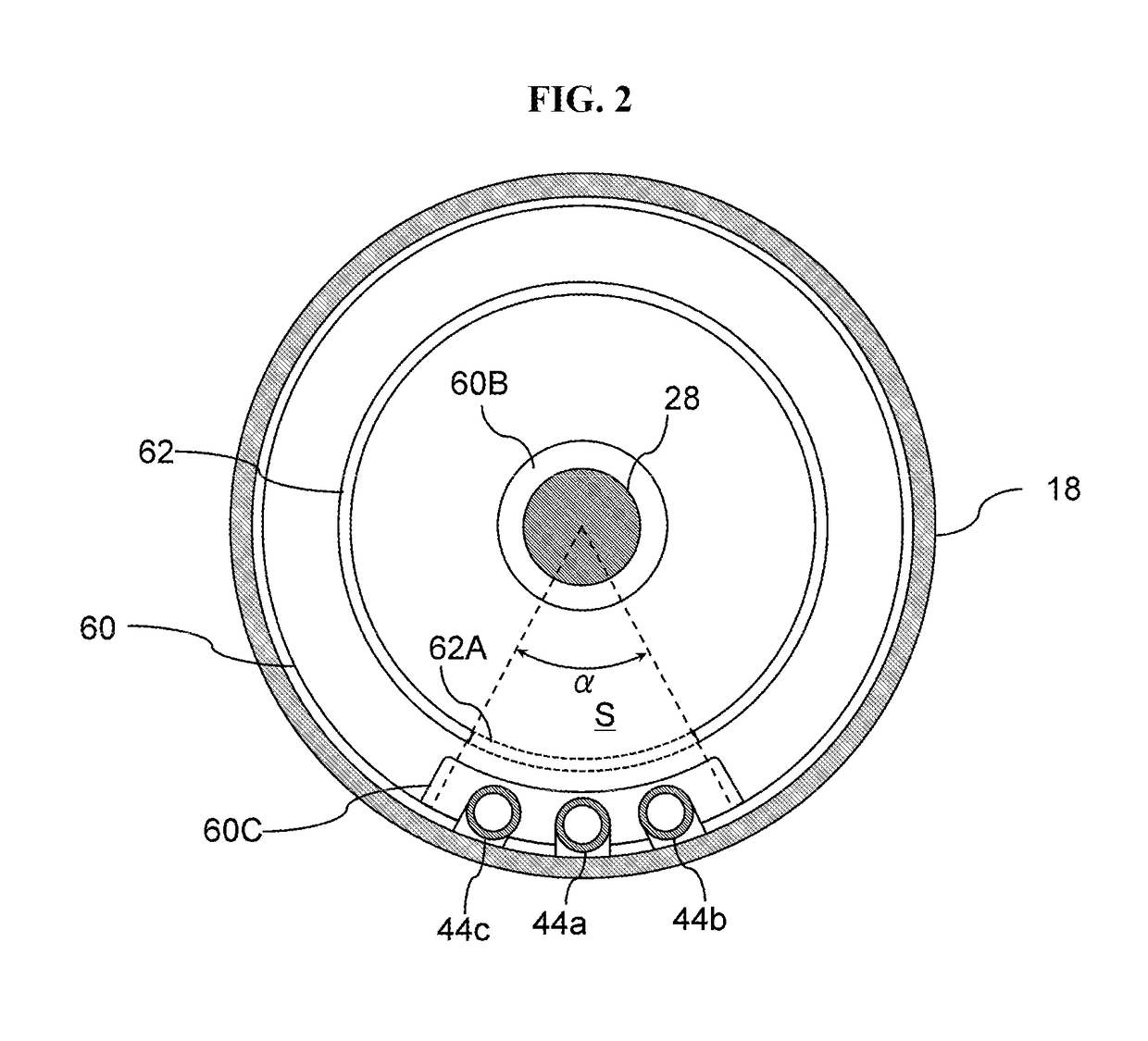
[0079]As shown in FIG. 10, the notch 62A may be provided at a plurality of locations as well as a single location. That is, the purge gas may be guided by the plurality of notches 62A toward a region at the furnace opening where the gas is stagnated or a region with high gas concentration to locally purge the regions. Accordingly, the entirety of the furnace opening may be purged. As a result, the gas concentration may be more efficiently maintained at a concentration lower than the predetermined value throughout the furnace opening, and the adhesion of by-products may be suppressed.

second modified example

[0080]As shown in FIG. 11, a recess having a width greater than that of the restrictor 62 may be provided on the lower surface of the insulating structure 24 at a position corresponding to that of the restrictor 62. The upper end of the restrictor 62 may be inserted into the recess. The restrictor 62 may be provided on the lower surface of the insulating structure 24 to protrude downward toward the lid instead of being provided on the lid cover 60. When the restrictor 62 is provided on the lower surface of the insulating structure 24, the recess may be provided on the lid cover 60 at a position corresponding to that of the restrictor 62 to engage with the restrictor 62. When the recess is provided, the flow path of the purge gas has a crank shape. As a result, the restrictor 62 may regulate the flow of the purge gas more efficiently with a crank-shaped gap compared to a straight gap of the same width. The width of the gap may be increased to more effectively regulate the flow of the...

third modified example

[0081]The flow rate of the purge gas may be increased or decreased while performing the steps of the film-forming process. By increasing the flow rate, localized purging may be enhanced. For example, the flow rate of the purge gas supplied to purge the furnace opening in the source gas supply step may be higher than that of the purge gas supplied to purge the furnace opening in the reactive gas supply step. With this configuration, the portion that is difficult to be purged may be efficiently purged.


PUM


Abstract

A technique capable of preventing by-products from adhering to a lower portion of a process vessel utilizes a substrate processing apparatus including: a process vessel having a process chamber; a lid configured to close a lower end opening of the process vessel; a substrate retainer; an insulating structure; a process gas supply mechanism configured to supply a process gas; a purge gas supply unit configured to supply a purge gas to a lower region of the process vessel via a gap between the insulating structure and the lid; and a restrictor disposed in the gap. The restrictor regulates flow of the purge gas such that the flow rate of the purge gas supplied to a first portion of the lower region of the process vessel is greater than a flow rate of the purge gas supplied to a second portion of the lower region of the process vessel.

Description


Claims


Application Information

Patent Timeline
Owner KOKUSA ELECTRIC CO LTD
Why Eureka
Try Eureka