Voltage source converter and control thereof

a voltage source converter and voltage source technology, applied in the field of voltage source converters, can solve the problems of high loss of conversion, complex drive circuitry, and high level of electromagnetic interferen

Inactive Publication Date: 2018-02-01
GENERAL ELECTRIC TECH GMBH
View PDF21 Cites 3 Cited by
  • Summary
  • Abstract
  • Description
  • Claims
  • Application Information

AI Technical Summary

Problems solved by technology

In high voltage applications where a large number of series connected IGBTs are required the approach does however require complex drive circuitry to ensure that the IGBTs switch at the same time as one another and requires large passive snubber components to ensure that the high voltage across the series connected IGBTs is shared correctly.
These factors can lead to relatively high losses in conversion, high levels of electromagnetic interference and a complex design.
This could be for instance due to some abnormal operating conditions such as those caused by grid fault.
This results in a rapid drop of current through the relevant converter arm, with an equally rapid rise in current through the other converter arm of the phase limb.
This induced voltage can lead to a voltage stress on the arm switching elements and potentially an overvoltage on the arm switching elements 110, e.g. the IGBTs.
In some instances, the collector to emitter voltage VCE could reach fault-level values outside the Safe Operating Area (SOA) that could potentially destroy them.
As will be described in more detail below in some embodiment modulations schemes, especially for controlling the harmonics, e.g. tripplen harmonic injection, may result in an increased voltage stress on a director switch during hard switching.

Method used


Image

  • Voltage source converter and control thereof
  • Voltage source converter and control thereof
  • Voltage source converter and control thereof

Examples


Embodiment Construction

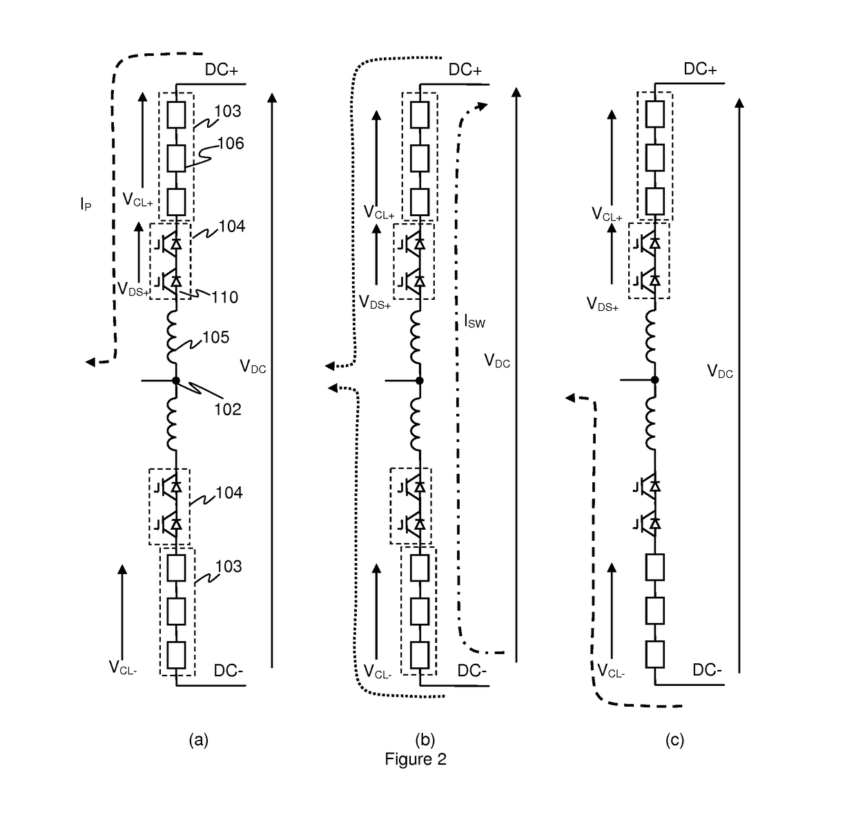
[0053]As mentioned above hard switching involves initiating turn-off of the director or arm switch of a converter arm at a point in the cycle when it is conducting current. With conventional hard switching this could, in some instances, lead to an over-voltage on the switching elements of the director switch.

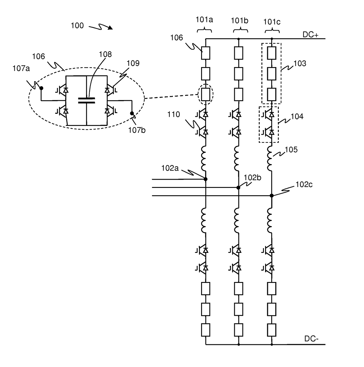
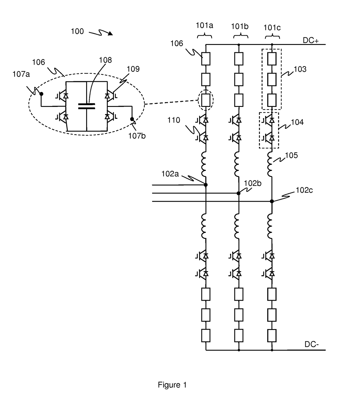
[0054]FIG. 2 illustrates how current flow may vary in a phase limb in a hard switching event. FIG. 2 illustrates a single phase limb of a voltage source converter (VSC) of the Alternative Arm Converter (AAC) type such as illustrated in FIG. 1. In FIG. 2 similar components to those shown in FIG. 1 are identified using the same reference numerals.

[0055]FIG. 2a illustrates the situation where the high side converter arm is conducting, with the high side director switch 104 being on or closed, and the low side director switch 104 off and non-conducting, e.g. as may be experienced in normal operation during at least some of the positive part of the AC cycle for the relevant phase. A ...


PUM


Abstract

Methods and apparatus for hard switching of Alternate-Arm-Converter voltage source converters. Such voltage source converters have a phase limb with a high and low side converter arm connecting an AC terminal to a high and low side DC terminal, respectively comprising a chain-link circuit in series with a director switch. Each chain-link circuit comprises series connected cells that can be switched to generate a controlled voltage across the chain-link circuit. In embodiments, a controller turns-off the director switch of a converter arm that is conducting current in response to a hard-switching request for a first phase limb. In response to a hard-switching request, the controller controls the chain-link circuits of the first phase limb at any point in a phase cycle to control: a DC voltage across the director switch; and / or the current flowing through the director switch to a predetermined level before turning the director switch off.

Description

FIELD OF INVENTION[0001]This application relates to a voltage source converter and to methods and apparatus for control of a voltage source converter, and especially to a voltage source converter for use in high voltage power distribution and in particular to hard switching of a voltage source converter.BACKGROUND OF THE INVENTION[0002]HVDC (high-voltage direct current) electrical power transmission uses direct current for the transmission of electrical power. This is an alternative to alternating current electrical power transmission which is more common. There are a number of benefits to using HVDC electrical power transmission.[0003]In order to use HVDC electrical power transmission, it is typically necessary to convert alternating current (AC) to direct current (DC) and back again. To date most HVDC transmission systems have been based on line commutated converters (LCCs), for example such as a six-pulse bridge converter using thyristor valves. LCCs use elements such as thyristo...

Claims


Application Information

Patent Timeline
Patent Type & Authority Applications(United States)
IPC IPC(8): H02M7/217H02M1/08
CPCH02M7/217H02M1/08H02J3/36H02M2001/0054H02M7/483H02M1/0054H02M7/4835Y02E60/60Y02B70/10H02M1/0095
Inventor CHIVITE ZABALZA, FRANCISCO JAVIERMORENO MUNOZ, FRANCISCOTRAINER, DAVID REGINALD
Owner GENERAL ELECTRIC TECH GMBH
Why Eureka
Try Eureka