
System and method for forming directionally solidified part from additively manufactured article

Pending Publication Date: 2018-02-08
HONEYWELL LKGLOBAL
View PDF5 Cites 4 Cited by
  • Summary
  • Abstract
  • Description
  • Claims
  • Application Information

AI Technical Summary

Benefits of technology

The patent discusses a method and system for manufacturing a directionally solidified article with a single-crystal structure using additive manufacturing and encasement techniques. The method involves providing a collection of particulate material and additively manufacturing a first article with an outer wall that defines a cavity containing an amount of particulate material. The first article is then encased with an outer member to form an internal cavity that corresponds to the first article. The method further involves heating the outer member and the first article to melt the first article into a molten mass within the internal cavity of the outer member and solidifying the molten mass along a predetermined solidification path within the outer member to form a second article that corresponds to at least a portion of the internal cavity of the outer member. The second article has a single-crystal structure and is formed by removing the trim portion from the first portion. The technical effect of the patent is the ability to manufacture directionally solidified articles with a single-crystal structure using additive manufacturing and encasement techniques.

Problems solved by technology

Manufacture of such parts may be difficult, expensive, time consuming, or otherwise problematic.
However, formation of the casting may present problems, especially when the part to-be-formed (e.g., a turbine blade, nozzle, or other component of a gas-turbine engine) has complex geometry.

Method used


Image

  • System and method for forming directionally solidified part from additively manufactured article
  • System and method for forming directionally solidified part from additively manufactured article
  • System and method for forming directionally solidified part from additively manufactured article

Examples


Embodiment Construction

[0022]The following detailed description is merely exemplary in nature and is not intended to limit the present disclosure or the application and uses of the present disclosure. Furthermore, there is no intention to be bound by any theory presented in the preceding background or the following detailed description.

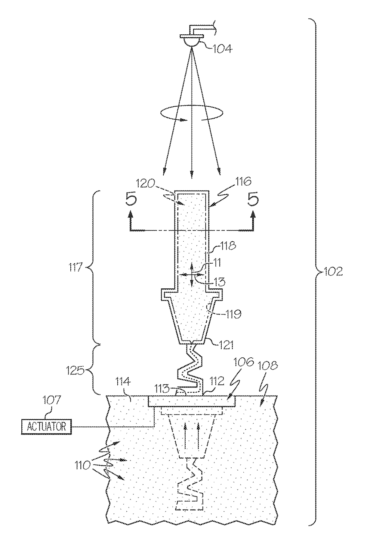
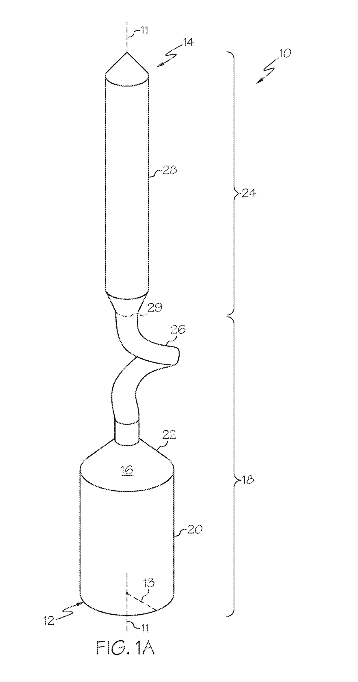
[0023]Referring initially to FIG. 1A, a part 10 is shown according to exemplary embodiments of the present disclosure. The part 10 may be formed using the system 100 represented schematically in FIG. 2 and according to the manufacturing method 1000 represented in FIG. 3.

[0024]As will be discussed, the part 10 may be formed in a specific and controlled manner For example, the part 10 may be solidified from a molten material in a predetermined manner. For example, in some embodiments, the part 10 may be directionally solidified as will be discussed in detail below. Accordingly, the material structure of the part 10 may include relatively few crystals and / or relatively few gra...


PUM

PropertyMeasurementUnit
Thicknessaaaaaaaaaa
Massaaaaaaaaaa
Volumeaaaaaaaaaa

Abstract

A method of manufacturing a directionally solidified article of the present disclosure includes providing a collection of particulate material and additively manufacturing a first article with an outer wall from the particulate material. The outer wall defines at least part of a cavity. The cavity contains an amount of the particulate material. The method also includes encasing at least a portion of the first article with an outer member. The outer member defines an internal cavity that corresponds to the first article. The method further includes heating the outer member and the first article to melt the first article into a molten mass within the internal cavity of the outer member. Additionally, the method includes solidifying the molten mass along a predetermined solidification path within the outer member to form a second article that corresponds to at least a portion of the internal cavity of the outer member.

Description

TECHNICAL FIELD[0001]The present disclosure generally relates to directional solidification methods and systems and, more particularly, relates to a system and method for forming a directionally solidified part from an additively manufactured article.BACKGROUND[0002]Parts may be made in a controlled manner to have one or more material characteristics. For example, it may be beneficial for a gas-turbine engine to have parts made from a material relatively free from impurities. Also, it may be beneficial for these parts to have a crystal structure with relatively few grain boundaries (e.g., with a single-crystal structure). Such parts may increase the efficiency and / or the operating life of the engine.[0003]Manufacture of such parts may be difficult, expensive, time consuming, or otherwise problematic. For example, casting processes may be employed when manufacturing these parts. However, formation of the casting may present problems, especially when the part to-be-formed (e.g., a tur...

Claims


Application Information

Patent Timeline
IPC IPC(8): B22D27/04B33Y30/00B33Y40/00C30B29/52B05D3/02B05D7/14B22F3/00C30B11/00B33Y10/00B05D1/18
CPCB22D27/045B33Y10/00B33Y30/00B33Y40/00C30B29/52B05D3/0254B05D7/14B22F3/008C30B11/002B05D1/18B22F5/009B22F5/04C30B11/003B22F3/24B22F2998/10Y02P10/25B22F10/64B33Y40/20B22F5/007B22D23/06B22F12/10B22F10/66B22F10/25B22F10/28B22F2003/248B22F2003/247B22F5/003B29C64/255B29C64/295B29C64/20B29C64/153
Inventor MITTENDORF, DONBUI, THO X.OTALUKA, WILLMARTINEZ, EDWINWOODWARD, JOHNKASAL, YATHIRAJ
Owner HONEYWELL LKGLOBAL
Features
  • Generate Ideas
  • Intellectual Property
  • Life Sciences
  • Materials
  • Tech Scout
  • Unparalleled Data Quality
  • Higher Quality Content
  • 60% Fewer Hallucinations
Learn More