Determination of fluid parameters

a fluid parameter and measurement technology, applied in the direction of material thermal analysis, material testing goods, instruments, etc., can solve the problems of long measurement time, high acquisition and maintenance costs of devices, and inability to obtain measurement data in real time, so as to achieve compact and cost-effective device design

Active Publication Date: 2018-02-08
SENSIRION AG
View PDF0 Cites 5 Cited by
  • Summary
  • Abstract
  • Description
  • Claims
  • Application Information

AI Technical Summary

Benefits of technology

[0045]In some embodiments, the thermal flow sensor device is a CMOS flow sensor. This allows a particularly compact and cost efficient design of the device.

Problems solved by technology

Such devices are, however, expensive in acquisition as well as in maintenance.
Moreover, measurement times are long and consequently, the measurement data are not available in real time but has to be gathered intermittently.
This method is, however, not as precise as desired.

Method used


Image

  • Determination of fluid parameters
  • Determination of fluid parameters
  • Determination of fluid parameters

Examples


Embodiment Construction

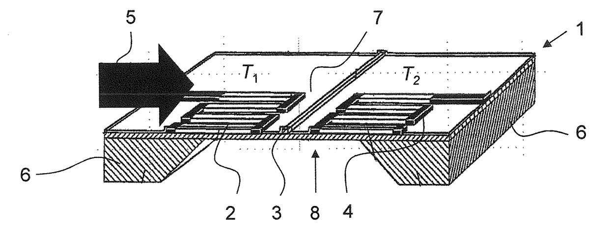
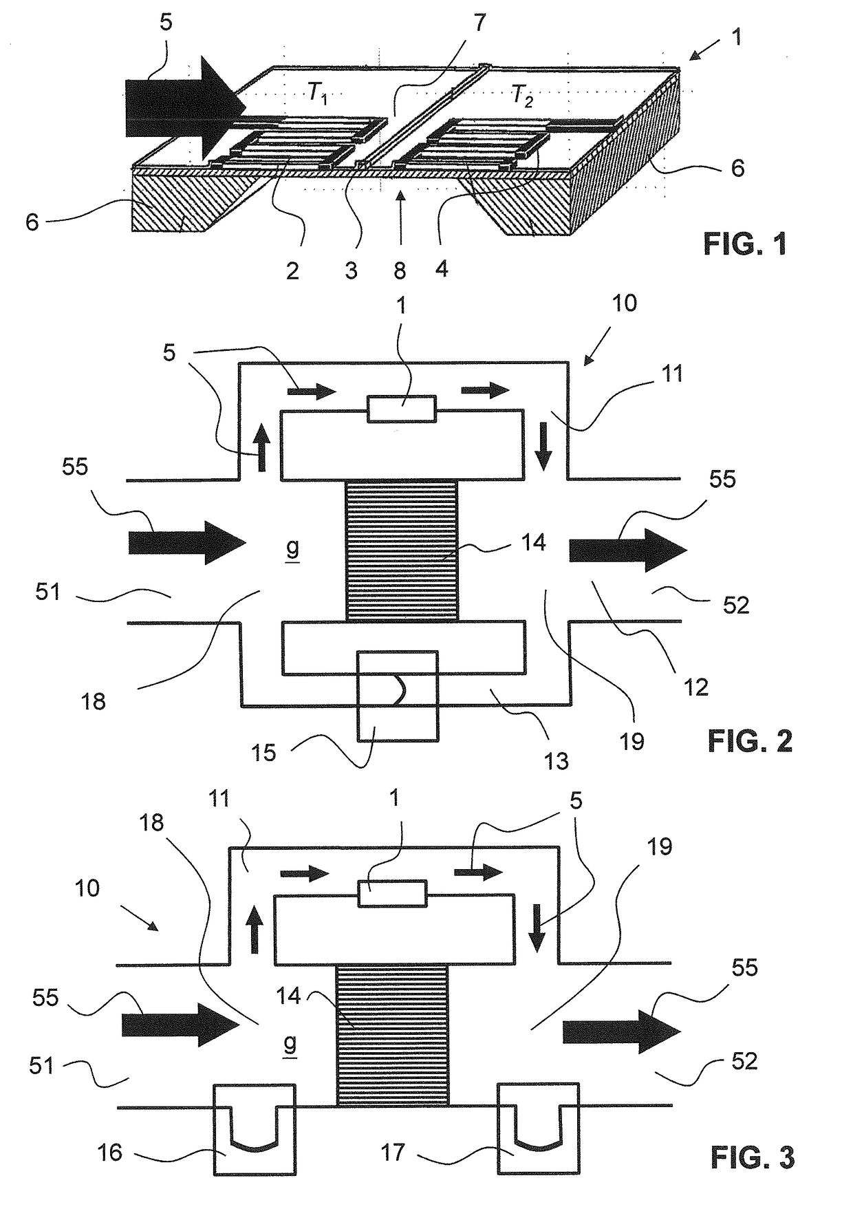
[0063]FIG. 1 shows a perspective view of a cross section of a thermal flow sensor 1 as described, e.g., in EP 1 426 740. The thermal flow sensor 1 comprises a substrate 6 (being preferably a semiconductor substrate, preferably from silicon). The substrate 6 is etched from one side to have a recess 8, wherein said recess 8 spanned by a membrane 7. On the membrane 7 are arranged, thermally well insulated, a first temperature sensor 2, a second temperature sensor 4, the second temperature sensor 4 being arranged downstream of the first temperature sensor 2, and a heater element 3, the heater element 3 being arranged being arranged between the two temperature sensors 2, 4.

[0064]The first temperature sensor 2 measures a first temperature T1, the second temperature sensor 4 a second temperature T2. In the present embodiment, the temperature sensors 2, 4 are thermopiles; in other embodiments, the temperature sensors 2, 4 may be of a different type, e.g. resistive temperature sensors. Typic...


PUM

PropertyMeasurementUnit
pressureaaaaaaaaaa
temperatureaaaaaaaaaa
absolute pressuresaaaaaaaaaa

Abstract

A method for determining fluid parameters, such as a heat capacity cpp, a calorific value Hp, a methane number MN, and/or a Wobbe index WI, of an unknown fluid (g). An unknown flow (55) of the fluid (g) is set in a sensor device (10), the sensor device (10) comprising a thermal flow sensor (1) and a pressure sensor device (15) for measuring at least one temperature value T1, T2, a further parameter, and differential pressure value Δρ over a flow restrictor (14). Using these measurement parameters T1, T2, Δp and calibration data, the calorific value Hp, and/or the Wobbe index WI, or parameters indicative thereof, of an unknown fluid (g) are calculated. The invention also relates to such a sensor device (10) and to a computer program product for carrying out such a method.

Description

TECHNICAL FIELD[0001]The present invention relates to a method for determining fluid parameters of an unknown fluid, in particular a calorific value of the fluid or a parameter related thereto, the fluid being preferably a burnable gas. It further relates to a measurement device and a computer program product configured to carry out said method.PRIOR ART[0002]Today's natural gas pipelines are organized in vast networks fed by numerous feed-in stations. As the gas in the pipeline system originates from different gas sources, the gas is naturally a mixture that varies over time.[0003]A calorific value of the natural gas is an important technical and economic fluid parameter that is commonly determined by analysis of the gas composition. The gas composition may be measured by means of a gas chromatograph. Such devices are, however, expensive in acquisition as well as in maintenance. Moreover, measurement times are long and consequently, the measurement data are not available in real ti...

Claims


Application Information

Patent Timeline
Patent Type & Authority Applications(United States)
IPC IPC(8): G01N25/00G01N33/22
CPCG01N25/005G01N33/225G01N25/20
Inventor HORNUNG, MARKRUEGG, ANDREAS
Owner SENSIRION AG
Why Eureka
Try Eureka