Lens barrel and imaging device

a technology of imaging device and lens barrel, which is applied in the direction of mountings, instruments, printing, etc., can solve the problems of inability to apply tilt mechanism, on an as-is basis, to lenses, and the amount of displacement of each lens' optical axis piles up, and it is difficult to make sufficient adjustments

Active Publication Date: 2018-02-08
RICOH IMAGING COMPANY
View PDF1 Cites 2 Cited by
  • Summary
  • Abstract
  • Description
  • Claims
  • Application Information

AI Technical Summary

Benefits of technology

[0008]It is an object of the present invention to provide a lens barrel that is comprised of a number of lenses, and that makes it possible to adjust the inclination of two or more lenses among these. Also, it is an object of the present invention to provide a lens barrel with an inclination adjustment mechanism that allows reliable inclination adjustments. Furthermore, the present invention provides an imaging device, such as a camera, with this lens barrel.

Problems solved by technology

Given a lens barrel that is comprised of a number of lenses, when tilt adjustments are applied to a number of lenses, although it is possible to make tilt adjustments with respect to lenses that are arranged at ends in the barrel-axis direction, these tilt mechanisms cannot be applied, on an as-is basis, to lenses that are arranged halfway in the optical axis direction inside the lens barrel.
As mentioned above, when a lens barrel is formed with multiple lenses, there is a problem that the amount of displacement of each lens's optical axis piles up, and therefore more meticulous tilt adjustments need to be made.
However, the places where tilt adjustments can be made with the tilt mechanisms of Patent Literature 1 and Patent Literature 2 are limited, which makes sufficient adjustments difficult.
Furthermore, not any lenses can be used for tilt adjustments, and tilt adjustments need to be made using lenses that are sensitive enough for adjustments.
When parts that are subject to adjustments are limited, this might result in a limited optical design, taking into consideration the locations where adjustments can be made and the sensitivity of lenses, and therefore the flexibility of design decreases.
Furthermore, although, according to both Patent Literature 1 and Patent Literature 2, the lens group located nearest the photographing object side is subject to adjustments, given the constraints in the design of lenses, the lens group located nearest the photographing object side is likely to have a large lens diameter, and tends to be large in mass.
When adjustments are made in one place on the photographing object side like this, constraints in design, such as the diameter of lenses, the mass of lenses and so on make the flexibility of design even lower.
Furthermore, when lenses have a large diameter and large in mass, if an impact and so on are applied after adjustments are made, the lenses are likely to be out of position, and, besides, given the problem that accurate adjustments are difficult to achieve by making adjustments in one place, it has heretofore been difficult to make meticulous tilt adjustments with conventional methods.

Method used


Image

  • Lens barrel and imaging device
  • Lens barrel and imaging device
  • Lens barrel and imaging device

Examples


Embodiment Construction

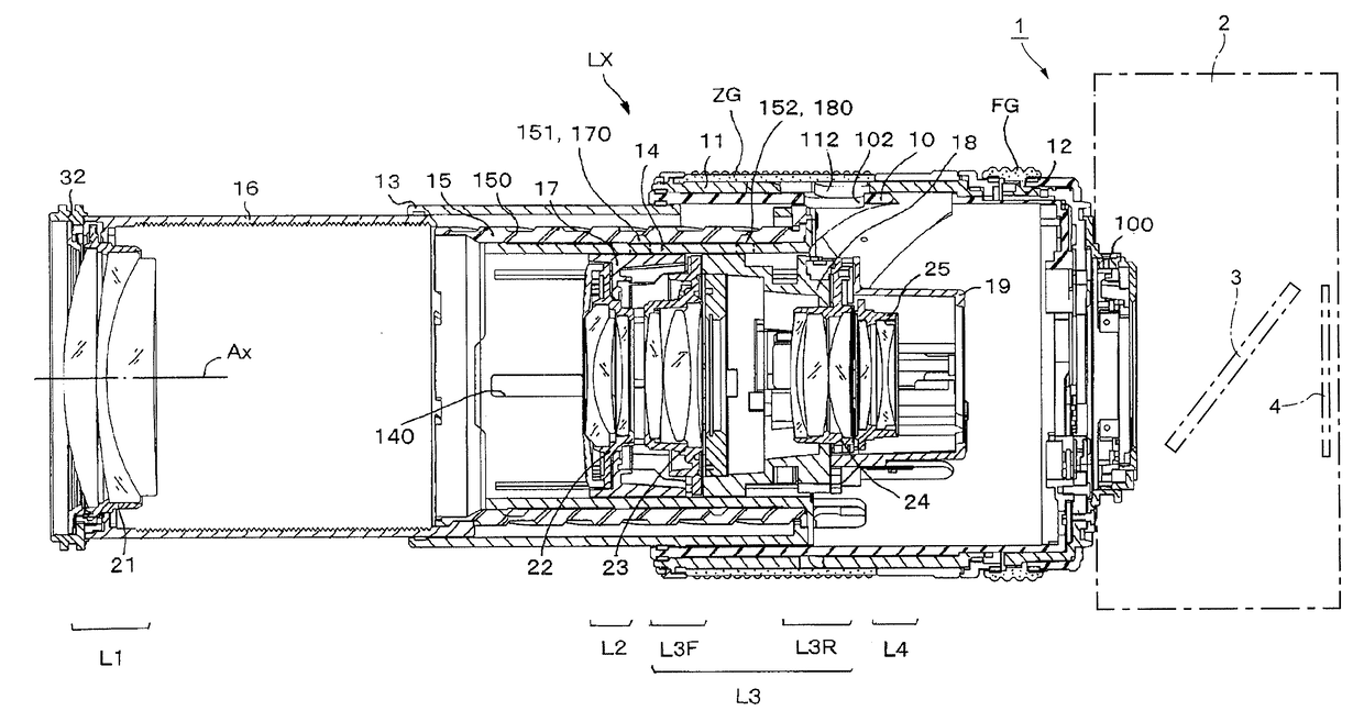
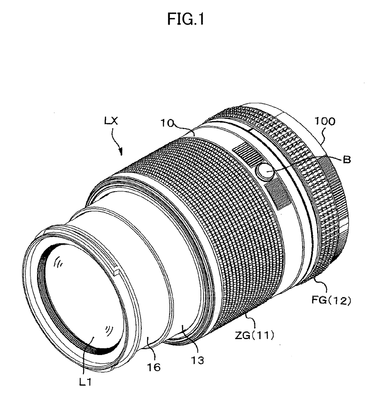
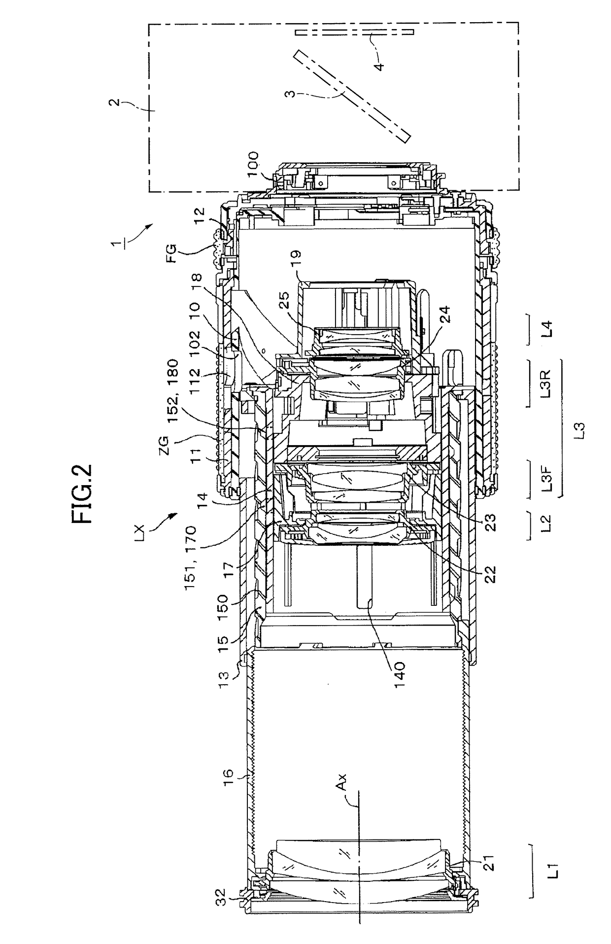
[0031]An embodiment of the present invention will be described with reference to the accompanying drawings. FIG. 1 is an outer perspective view of a lens barrel LX according to the present invention, formed as a zoom interchangeable lens for a single-lens reflex camera (imaging device) 1 (see FIG. 2 and FIG. 3).

[0032]A camera body 2 of the single-lens reflex camera 1 is provided on the front thereof with a lens mount to which the lens barrel LX is detachably attached. The camera body 2 is provided thereinside at a position behind the lens mount with a quick-return mirror 3 and an image sensor 4.

[0033]The lens barrel LX can be attached to / removed from the camera body 2 by means of a lens mount 100 that is provided in a fixing barrel 10, and can move to the long-focus (telephoto) side and the short-focus (wide-angle) side by rotating / operating a zoom ring 11. Also, by operating the zoom ring 11 further to the short-focus side while pressing a retraction button B disposed in an outer p...


PUM


Abstract

A number of lenses are provided in a lens barrel along the optical axis direction, and two lenses, among the multiple lenses, are structured so that their inclination can be adjusted independently. Tilt adjustments for a lens frame of one lens, which is arranged on the opening side of the lens barrel in the optical axis direction, can be made through an opening of the lens barrel. The other lens frame of the other lens, which is arranged in the middle of the multiple lenses, is structured so that inclination adjustments can be made through throughholes that are provided to penetrate the peripheral surface of the lens barrel in the diameter direction.

Description

FIELD OF THE INVENTION[0001]The present invention relates to a lens barrel that can adjust the optical axis of lenses provided in the barrel, and an imaging device that takes a still image or a movie of a photographing object by using the lens barrel.DESCRIPTION OF THE RELATED ART[0002]The lens barrel of an imaging device—for example, a single-lens reflex camera—is formed by assembling a number of lenses in a barrel that is formed in a cylindrical shape. These multiple lenses are each formed with a single-element lens or a lens group that combines a number of single-element lenses. Here, these single-element lenses and lens groups will be referred to as “lenses.” In this way, when a number of lenses are provided in a lens barrel, in order to improve the image quality of photographed images, such as aberration performance, it is necessary to make adjustments so that the optical axis of each lens matches or assumes a predetermined positional relationship. The optical axis of each lens...

Claims


Application Information

Patent Timeline
Patent Type & Authority Applications(United States)
IPC IPC(8): G02B7/04G02B7/02
CPCG02B7/04G02B7/026G02B7/021G02B7/023G03B5/06G03B17/14G03B17/565
Inventor SUZUKI, YOHSUKE
Owner RICOH IMAGING COMPANY
Why Eureka
Try Eureka