Digital camera focus assembly

a technology of digital camera and assembly, applied in the direction of camera focusing arrangement, printers, instruments, etc., can solve the problem of reducing the overall thickness of a portable electronic device, and achieve the effect of reducing input voltage, reducing weight, and reducing vcm

Inactive Publication Date: 2018-02-08
MICROSOFT TECH LICENSING LLC
View PDF4 Cites 27 Cited by
  • Summary
  • Abstract
  • Description
  • Claims
  • Application Information

AI Technical Summary

Benefits of technology

[0003]In some examples, a focus assembly of a digital camera function adjusts focus of an image to be captured by moving an image sensor relative to a fixed lens assembly. To move the image sensor, an image sensor drive, such as a voice coil motor (VCM), may be activated by an input voltage supplied by a digital-to-analog converter (DAC). In some instances, the image sensor may be lighter weight and / or smaller than the lens assembly, such that a smaller VCM and lower input voltage can be used than is needed for conventional focus assemblies in which the lens assembly is moved relative to a fixed image sensor.
[0004]In some examples, the lens assembly may be affixed to a housing of the focus assembly and light entering through the lens assembly may be reflected at an angle to be received in an area away from the area immediately behind the lens assembly. In that case, multiple lens assemblies can be used and the light may be reflected more than once to reach a desired location where the image sensor is positioned. The light may be optically treated or processed, such as filtering and zooming, with an optical device placed between the lens assemblies before reaching the movable image sensor. This arrangement may allow for greater movement of the image sensor relative to at least a portion of the lens assembly.
[0005]In some examples, to further reduce the thickness of the focus assembly, the image sensor drive may be positioned between the lens assembly and the movable image sensor. For instance, the image sensor drive may be positioned concentric with at least a portion of the lens assembly. In some examples, this may reduce the overall thickness of a portable electronic device in which the focus assembly is installed.

Problems solved by technology

In some examples, this may reduce the overall thickness of a portable electronic device in which the focus assembly is installed.

Method used


Image

  • Digital camera focus assembly
  • Digital camera focus assembly
  • Digital camera focus assembly

Examples


example clauses

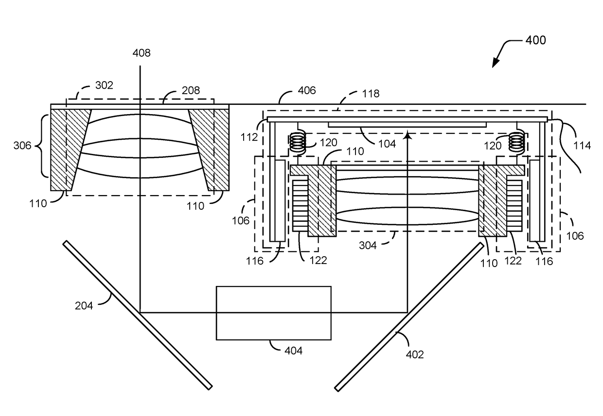
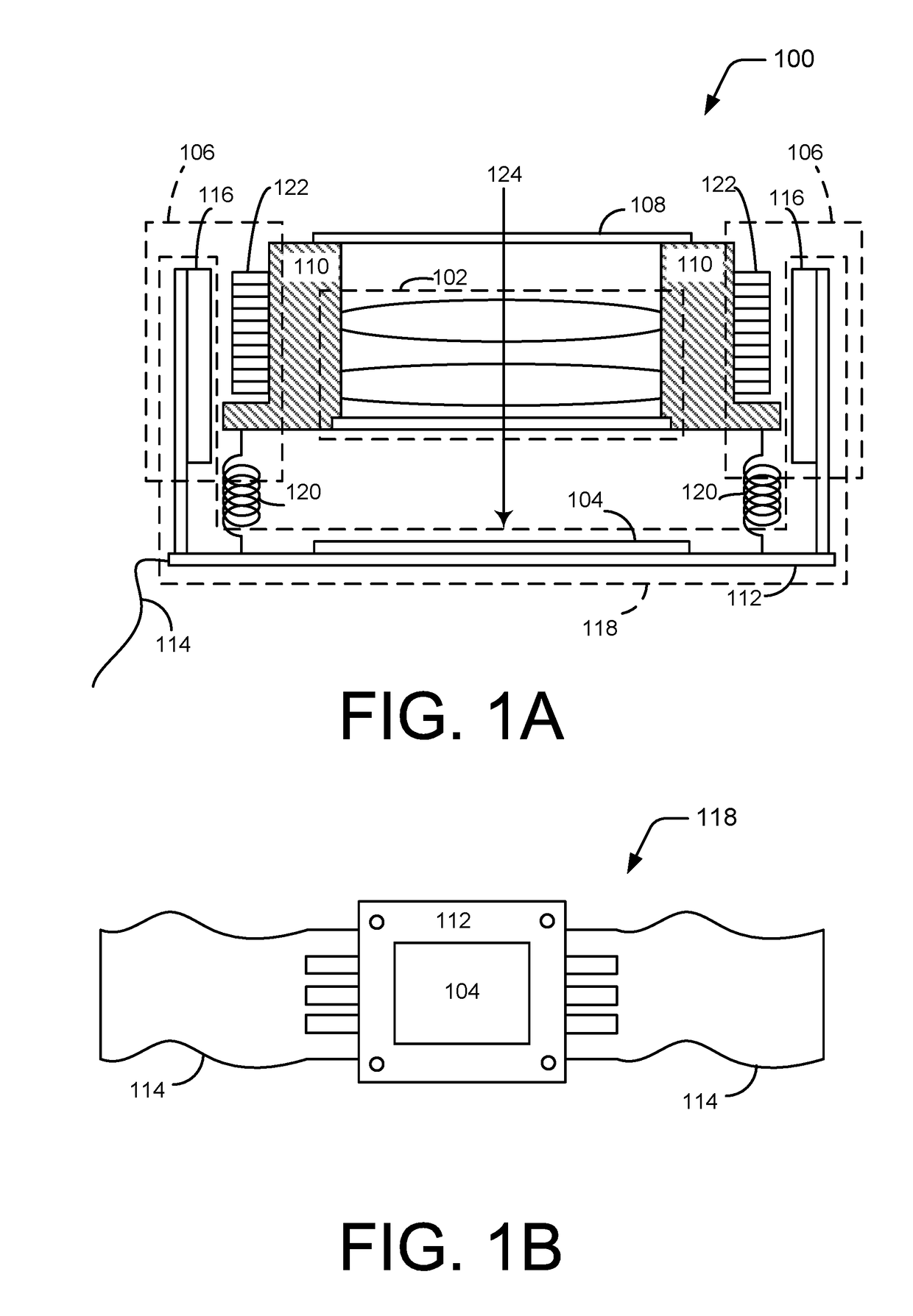
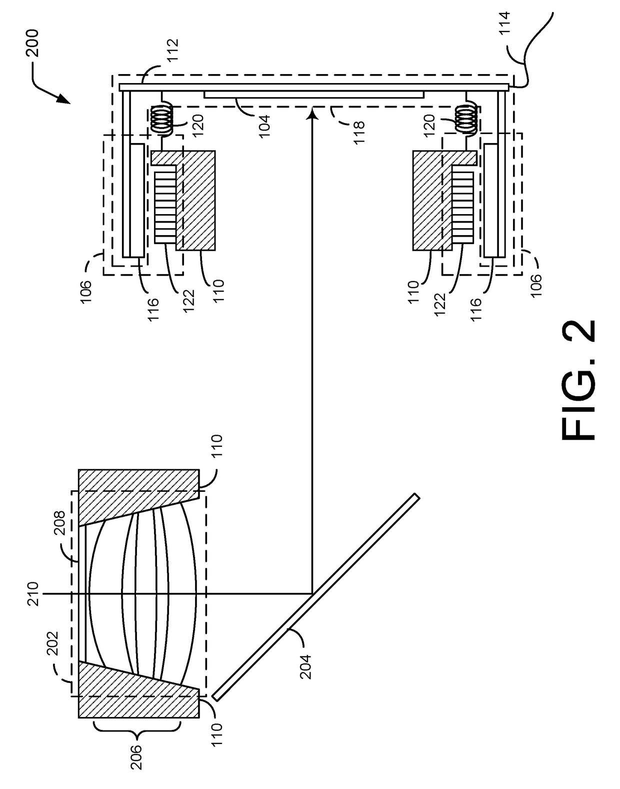
[0040]A. A digital camera focus assembly comprising: a housing; a lens assembly disposed in and affixed to the housing to receive light; a movable image sensor assembly disposed in the housing and configured to receive the light from the lens assembly and to generate an image associated with the light, the movable image sensor assembly being movable along a path of the light relative to the lens assembly; and an image sensor drive disposed in the housing and coupled to the image sensor, the image sensor drive positioned in parallel with at least a portion of the lens assembly between the lens assembly and the movable image sensor assembly, the image sensor drive configured to move the movable image sensor assembly relative to the lens assembly to adjust a focus of the light resolved at the image sensor.

[0041]B. A digital camera focus assembly as paragraph A recites, further comprising a flexible printed circuit board coupling the movable image sensor assembly to one or more processo...


PUM


Abstract

In a portable electronic device having a digital camera function, focusing of an image may be accomplished by moving a movable image sensor assembly relative to a lens assembly that is affixed in a housing. An image sensor drive, such as a voice coil motor to move the movable image sensor assembly, may be positioned between the movable image sensor assembly and the lens assembly concentric with the lens assembly.

Description

BACKGROUND[0001]In addition to digital cameras, digital camera function has become widely available as a built-in function for many portable electronic devices such as cellular phones, tablet computers, and laptop computers. Typically, the camera lens assembly, is located on the back side, on the front side, or both the front and back of the portable electronic device. As these portable electronic devices become thinner and more complex with additional features, providing a sufficient range of the lens assembly movement for focusing becomes more difficult to achieve. Due to the thickness of the portable electronic device, a typical single lens assembly does not allow for more complex lens arrangement, and the drive mechanism must be able to provide sufficient force to balance the weight of the lens assembly and to achieve fast and accurate focus adjustments.BRIEF SUMMARY[0002]This Summary is provided in order to introduce simplified concepts of the present disclosure, which are furt...

Claims


Application Information

Patent Timeline
Patent Type & Authority Applications(United States)
IPC IPC(8): H04N5/225H04N5/232
CPCH04N5/2252H04N5/23212H04N5/2254H04N5/2253G03B3/00G03B3/04G03B3/10H04N23/55H04N23/67H04N23/51H04N23/54
Inventor CUI, CHENGWU
Owner MICROSOFT TECH LICENSING LLC
Why Eureka
Try Eureka