
Terminal device, base station device, and method

a technology of base station and terminal device, applied in the direction of payload allocation, transmission path sub-channel allocation, machine-to-machine/machine-type communication service, etc., can solve the problems of not being able to realize or becoming difficult to realize functions that have been conventionally realized, and achieve the effect of improving transmission efficiency

Active Publication Date: 2018-02-08
SHARP KK
View PDF9 Cites 48 Cited by
  • Summary
  • Abstract
  • Description
  • Claims
  • Application Information

AI Technical Summary

Benefits of technology

The invention improves how well radios can communicate with each other in a system where there is a base station and a terminal device. This makes it easier for information to be transmitted between them.

Problems solved by technology

In NPL 1, when reducing the cost of the machine type communication, it may not be able to realize or may become difficult to realize functions that have been conventionally realized.

Method used


Image

  • Terminal device, base station device, and method
  • Terminal device, base station device, and method
  • Terminal device, base station device, and method

Examples


first embodiment

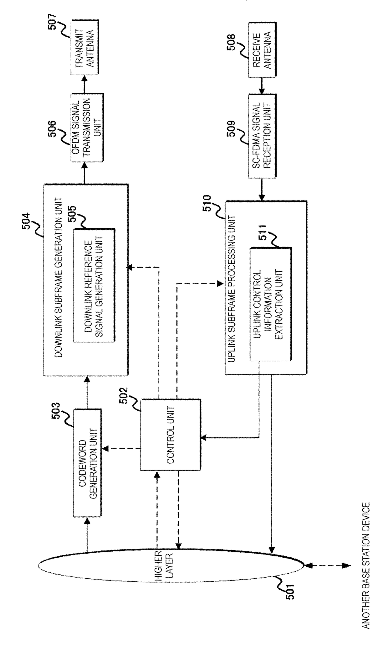
[0019]A first embodiment of the present invention will be described below. Description will be given by using a communication system in which a base station device (base station, NodeB, or EUTRAN NodeB (eNB)) and a terminal device (terminal, mobile station, user device, or user equipment (UE)) communicate in a cell.

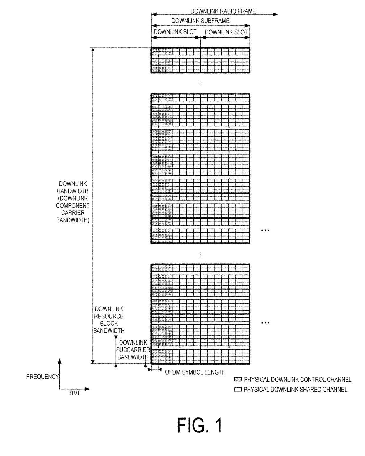
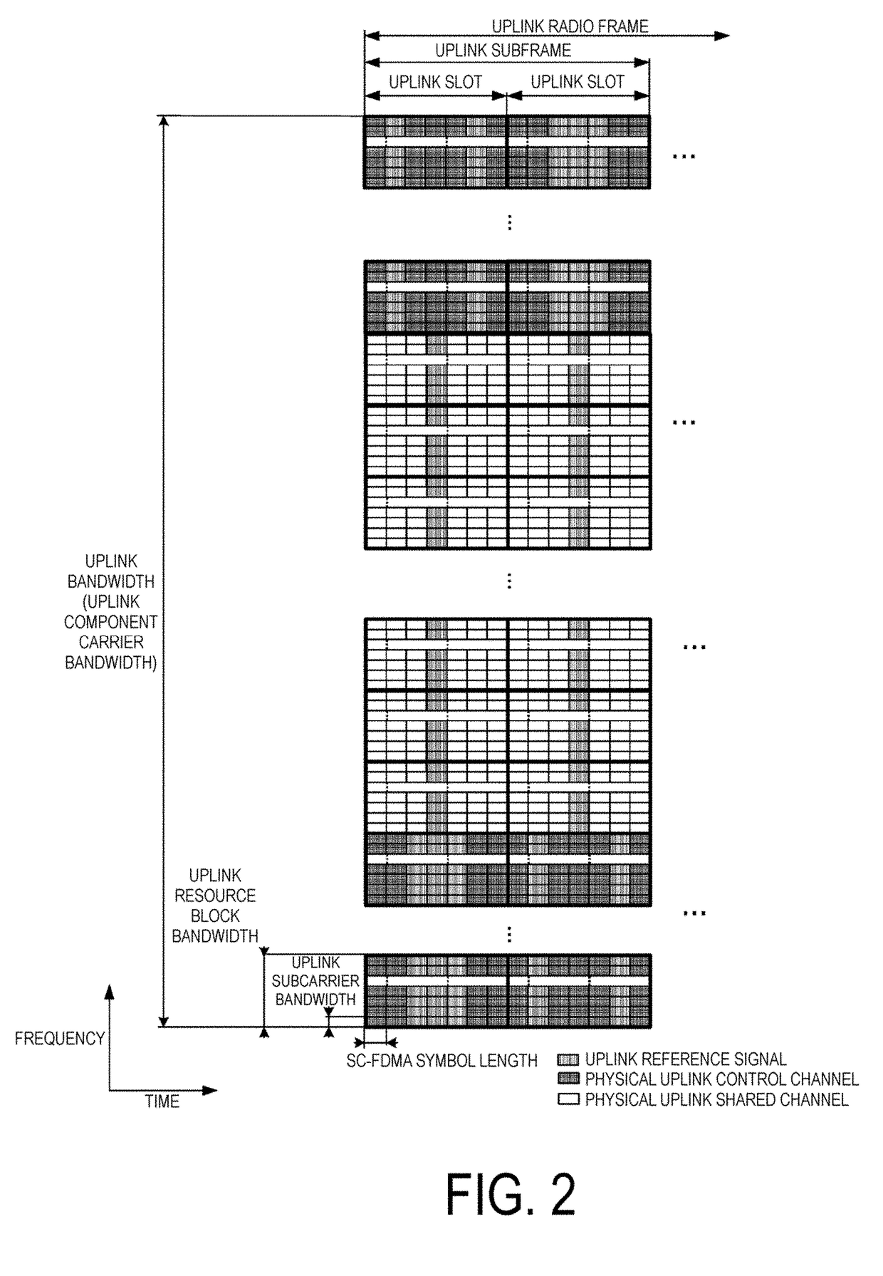
[0020]Main physical channels and physical signals used in the EUTRA and the A-EUTRA will be described. The “channel” refers to a medium used to transmit a signal, and the “physical channel” refers to a physical medium used to transmit a signal. In the present embodiment the “physical channel” may he used as a synonym of “signal.” In the future EUTRA and A-EUTRA, another physical channel may be added, the constitution or format of the existing physical channel may be changed, or another constitution or format may be added; however, the description of each embodiment of the present invention will not be affected even if such addition or change is performed.

[0021]In the EUTR...


PUM


Abstract

In order to perform efficient communications, provided is a terminal device configured to communicate with a base station device. The terminal device includes: a reception unit configured to receive a higher layer signal including a configuration relating to a physical uplink shared channel (PUSCH); a scrambling sequence generator configured to, if the terminal device supports a capability relating to low complexity and / or coverage enhancement, apply the same scrambling sequence to the PUSCH during a certain period; and a transmission unit configured to transmit the PUSCH, on the basis of the number of repetitions in the configuration relating to the PUSCH.

Description

TECHNICAL FIELD[0001]Embodiments of the present invention relate to a technique for a terminal device, a base station device, and a method that enable efficient sharing of channel state information.[0002]This application claims priority from Japanese Patent Application No. 2015-014729, filed in Japan on Jan. 28, 2015; the entire contents of which are incorporated herein by reference.BACKGROUND ART[0003]The 3rd General Partnership Project (3GPP), which is a standardization project has standardized the Evolved Universal Terrestrial Radio Access (EUTRA), in which high-speed communication is realized by adopting an orthogonal frequency division multiplexing (OFDM) communication scheme and flexible scheduling in a unit of prescribed frequency and time called a resource block. The overall communications that have employed the standardized EUTRA technology may be referred to as “Long Term Evolution (LIE) communications.”[0004]Moreover, the 3GPP discusses the Advanced EUTRA (A-EUTRA), which...

Claims


Application Information

Patent Timeline
Patent Type & Authority Applications(United States)
IPC IPC(8): H04W4/00H04W72/12H04W8/24H04W4/70
CPCH04W4/005H04W8/24H04W72/12H04W72/04H04W74/08H04L5/0044H04W4/70H04L5/0053
Inventor OUCHI, WATARUSHIMEZAWA, KAZUYUKIYAMADA, SHOHEIHAYASHI, TAKASHIKATO, YASUYUKIKUSASHIMA, NAOKIRUIZDELGADO, ALVAROIMAMURA, KIMIHIKO
Owner SHARP KK
Learn More