Formed denture and method of making same

a technology of dentures and dentures, applied in the field of dentures, can solve the problems of high labor intensity, improper occlusion of upper and lower teeth, and high labor intensity in the manufacture of dental prostheses, and achieve the effect of low cos

Active Publication Date: 2018-02-15
GLOBAL DENTAL SCI
View PDF0 Cites 22 Cited by
  • Summary
  • Abstract
  • Description
  • Claims
  • Application Information

AI Technical Summary

Benefits of technology

[0028]Additionally, the posterior teeth of the complete try-in denture may be adjusted for optimal occlusion by using articulating paper and a bur to locate “high spots” and then grinding each “high-spot” down in progressive steps. A jaw recording device, such as a Gothic Arch tracing system (e.g., a Massad Jaw Recorder) may be used to make this process efficient and accurate. The borders of the denture are evaluated for fit and adjusted as required. The patient may also comment on areas that feel tight or cause pressure on their dental ridge, and those areas can be adjusted, such as by grinding with a bur. In some cases, a pressure indicating paste may be used to determine where interferences are present, and then those interferences are adjusted. The optimally adjusted try-in denture is then removed from the patient, and a “final denture mold” of it is made. The adjusted try-in denture is removed from the final denture mold, and the anterior teeth and try-in gingival and anterior tooth waxes are removed (often using hot water and steam), resulting in a “semi-complete” denture.
[0030]In certain embodiments of fabrication of a denture according to the method, CADCAM design and milling of a denture base and posterior teeth, and the separate anterior teeth are used with CADCAM design and 3D-printing or milling of a first-milled denture for producing the initial molding and try-in denture formation steps. The method is advantageous in that it results in a better fitting and longer life denture that is completed in final form in less time than conventional denture fabrication methods. Additionally, the posterior teeth may be milled-away completely in the secondary milling step, and denture teeth can be substituted by placing the posterior teeth into the preliminary mold in the same steps as the anterior teeth, as described above. Additionally, for an “economy denture,” the second milling step may be combined in the first milling step and the anterior teeth may be left in place; instead, only the tooth-colored material in areas that should be tissue-colored are “cut-back.” In this case, the first-milled denture becomes the try-in denture or the final denture. However, in such an embodiment, the teeth can only be reduced in size by grinding with a handpiece; the position of the teeth cannot be moved.
[0044]In another embodiment, a denture may be fabricated from a first milling step performed on a block of denture material comprising a layer of denture base material and a layer of denture tooth material, with the denture base material being of a pink gum color, and the denture tooth material being white tooth colored material (and possibly having a translucency gradient), as described previously. Additionally, in the gingival portions proximate to the denture teeth that are formed of denture tooth material, those portions may be milled away to form gingival and lingual / palatal recesses. These recesses may subsequently be back-filled with gum colored denture base material to produce the final denture. Such a simple denture fabrication method is enabled by the use of the block of denture material comprising a layer of denture base material and a layer of denture tooth material as a starting block of material. The resulting denture is of low cost, and may be provided to a patient as an “economy denture” option.

Problems solved by technology

Heretofore, the manufacturing of dental prostheses has been a highly labor intensive process requiring multiple fittings to a patient in need of them, and many steps that must be performed at the hands of skilled artisans.
It can be seen that in the above highly labor-intensive process, each of these steps introduces a potential for a processing error.
Even the slightest error, such as the investment being too cool, or the powder / water ratio of the investment being incorrect, may cause the crown to fit too tightly in the patient's mouth, resulting in improper occlusion (upper and lower teeth engagement).
The crown may thus have to be scrapped or reworked through at least one iteration of additional process steps at considerable cost to the patient, dentist, and / or manufacturing lab.
For example, subtle irregularities often found in anterior (front) teeth are difficult to replicate using CAD / CAM processes.
Manual methods of making anterior fixed prosthetics enable unlimited aesthetic options, only limited by the creativity of the artisan (dental laboratory technician).
Some CAD / CAM techniques involve the use of milling a monolithic block of ceramic that does not deliver optimal aesthetics (example: too opaque), especially for anterior applications.
However, this manual step may defeat the primary benefit of CAD / CAM: precise dimensional accuracy.
However, this system generates only a CAD replica in plastic (made by a 3D printer), which requires subsequent extensive processing to obtain a metal partial denture framework.
Hence there are still many error-prone steps after the CAD replica is made that can result in a poorly-fitting partial denture framework.
However, the materials available to use in three-dimensional printers are neither as dense nor cross-linked like a normal plastic artificial tooth.
Hence a problem remains with the resulting dentures because the denture teeth that are made with available 3D printing plastic materials are not sufficiently wear-resistant.
The reason that this method cannot be used for long-term dentures is that the artificial teeth must be “glued” into position, thus this interface between the teeth and the base is susceptible to bacteria growth and debonding of the teeth from the base over time due to the oral fluids which may degrade the bonding material.
This extra labor is required because the exact position of the teeth cannot be assured in the manual “gluing” procedure.

Method used


Image

  • Formed denture and method of making same
  • Formed denture and method of making same
  • Formed denture and method of making same

Examples


Embodiment Construction

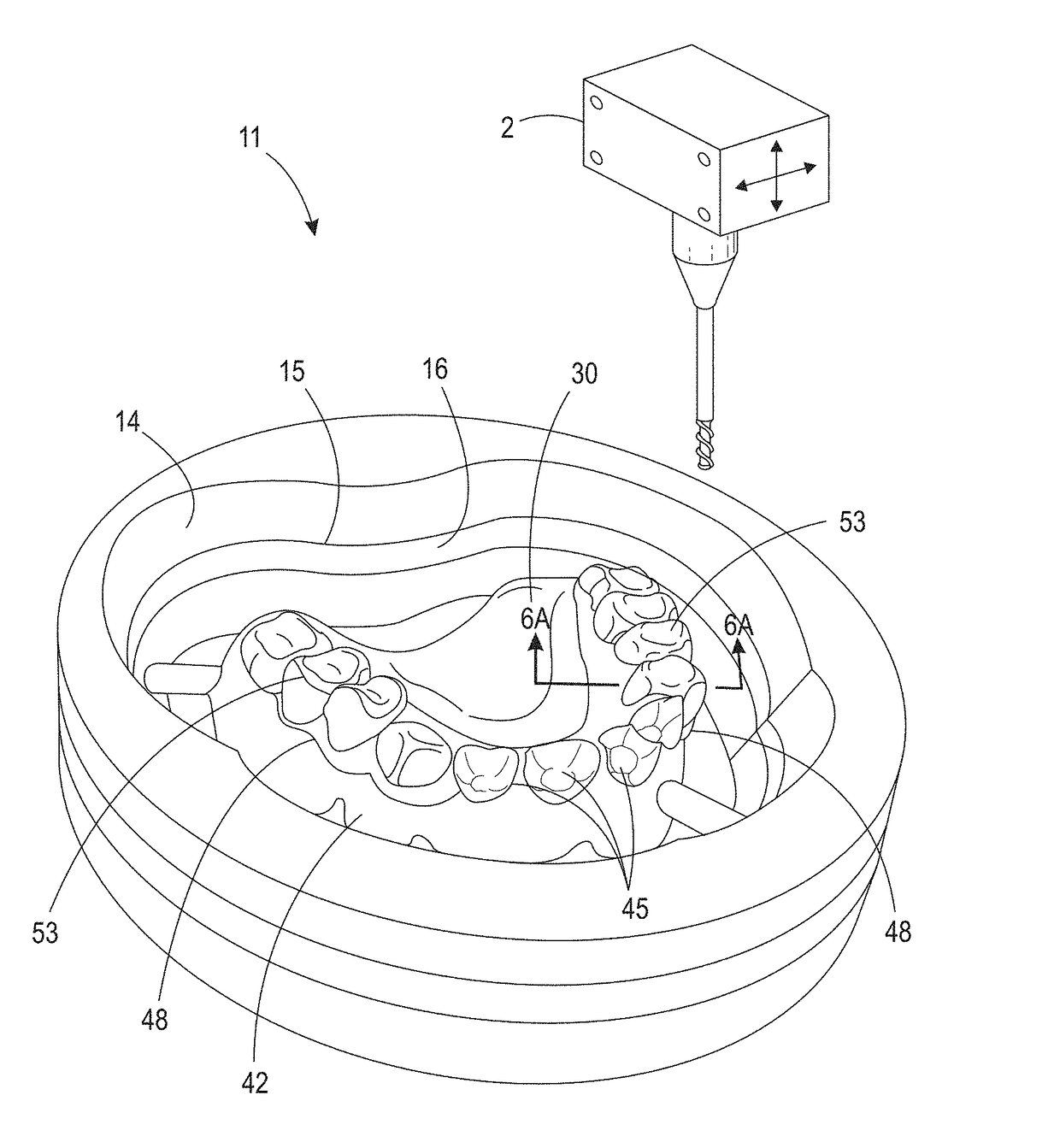
[0067]For a general understanding of the present invention, reference is made to the drawings. In the drawings, like reference numerals have been used throughout to designate identical elements. The drawings are to be considered exemplary, and are for purposes of illustration only. The dimensions, positions, order and relative sizes reflected in the drawings attached hereto may vary.

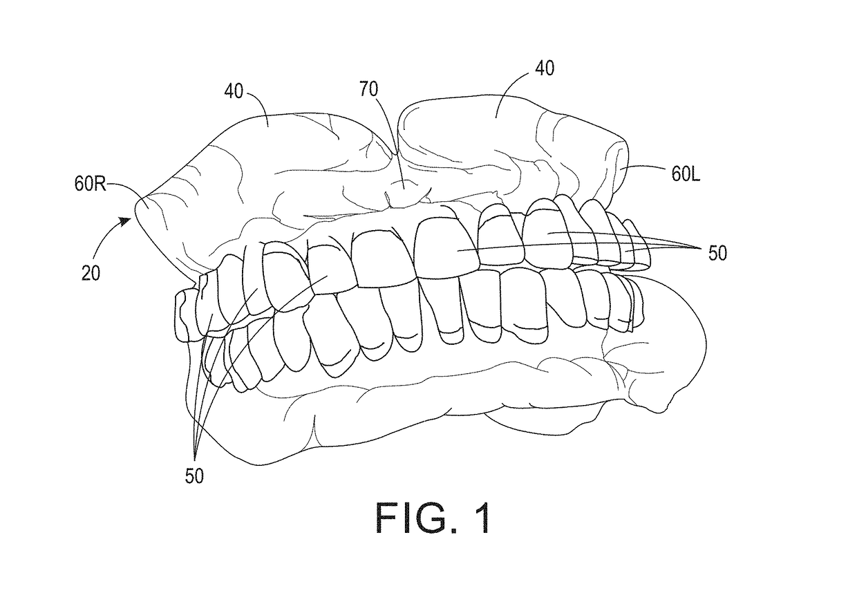
[0068]In the following disclosure, the methods of the present invention are described in the context of their use for fabrication of an upper denture, which includes a palatal region. However, they are not to be construed as being limited only to use in fabricating upper dentures. The methods are adaptable to fabrication of lower dentures as well as other dental prostheses. Additionally, the description may identify certain structures with the adjectives “top,”“upper,”“bottom,”“lower,”“left,”“right,” etc. These adjectives are provided in the context of use of the method in fabricating an upper denture, a...


PUM

PropertyMeasurementUnit
flexural strengthaaaaaaaaaa
depthaaaaaaaaaa
depthaaaaaaaaaa

Abstract

A method of fabricating a denture, comprising milling a preliminary try-in denture from denture material comprising a layer of denture base material contiguous with a layer of denture tooth material. Denture base material is removed from the block to form a first part of the, labial, buccal, gingival, and flange regions of the denture base to form a preliminary denture. A preliminary mold is created from this preliminary denture. The preliminary denture is then further modified with deformable waxes in gingival and anterior tooth recesses to form a preliminary try-in denture, which is fitted to a patient and adjusted to optimal dimensions. The adjusted try-in denture is then reproduced by further molding methods, producing the final denture.

Description

CROSS-REFERENCE TO RELATED PATENT APPLICATIONS[0001]This application claims priority to U.S. Patent Application No. 62 / 374,471, filed on Aug. 12, 2016, the disclosure of which is incorporated herein by reference.BACKGROUNDTechnical Field[0002]Dental prostheses and apparatus and methods of manufacturing them. In particular, computer-implemented methods of manufacturing dental prostheses, a computer-aided system for manufacturing dental prostheses, and dental prostheses made by the system and method.Description of Related Art[0003]Heretofore, the manufacturing of dental prostheses has been a highly labor intensive process requiring multiple fittings to a patient in need of them, and many steps that must be performed at the hands of skilled artisans. The dental prostheses may be a complete upper and / or lower set of prosthetic teeth and their mountings, i.e., complete dentures; or partial dentures, crowns, bridges, and the like.[0004]Advances have been made in Computer Aided Design and ...

Claims


Application Information

Patent Timeline
Patent Type & Authority Applications(United States)
IPC IPC(8): A61C13/107A61C13/34A61C13/00A61C13/01A61C13/08
CPCA61C13/0001A61C13/04A61C13/081A61C13/34A61C13/0022A61C13/0019A61C13/0004A61C13/082A61C13/10A61C13/1003
Inventor HOWE, DEVON O.
Owner GLOBAL DENTAL SCI
Why Eureka
Try Eureka