
Expandable sheath and methods of use

a sheath and expandable technology, applied in the field of expandable sheaths and methods of use, can solve the problems of increasing the amount of time the procedure takes, reducing the working length of the delivery apparatus, and increasing the risk of damage to the vessel, so as to reduce the lumen

Inactive Publication Date: 2018-02-15
ADVANCED CARDIOLOGY ENG SOLUTIONS LLC
View PDF5 Cites 26 Cited by
  • Summary
  • Abstract
  • Description
  • Claims
  • Application Information

AI Technical Summary

Benefits of technology

The patent describes a method for making a prosthetic device that can be inserted into a patient's body. The method involves using an inner member that can be partially collapsed to make the device fit tightly around a specific area, like a blood vessels. This helps to prevent the device from leaking or causing damage to the patient's body. The method can be used to make a variety of prosthetic devices, like stent grafts, that can be used to treat damaged blood vessels or other body parts.

Problems solved by technology

A conventional loader extends from the proximal end of the introducer sheath, and therefore decreases the available working length of the delivery apparatus that can be inserted through the sheath and into the body.
This repeated insertion and vessel dilation can increase the amount of time the procedure takes, as well as the risk of damage to the vessel.
Such introducer sheaths tend to have complex mechanisms, such as ratcheting mechanisms that maintain the shaft or sheath in an expanded configuration once a device with a larger diameter than the sheath's original diameter is introduced.
However, delivery and / or removal of the prosthetic devices and other materials to or from a patient can still poses a threat to a patient.
Furthermore, accessing the vessel remains a challenge due to the relatively large profile of the delivery system; bending or kinking can cause longitudinal and radial tearing of the vessel during insertion.
The delivery system can additionally dislodge calcified plaque within the vessel, posing a risk of clots caused by the dislodged plaque.
The addition of radially expanding properties can also hinder a practitioner's ability to push the introducer sheath without it bending or kinking.

Method used


Image

  • Expandable sheath and methods of use
  • Expandable sheath and methods of use
  • Expandable sheath and methods of use

Examples


Embodiment Construction

[0050]In some embodiments, expandable sheaths as disclosed herein can be used to deliver a prosthesis device through a patient's vasculature to a procedure / implantation site within the body. The sheath can be constructed to be highly expandable and collapsible in the circumferential / radial direction, while also minimizing the wall thickness of the sheath to minimize puncture size and / or accommodate a larger profile of the delivery system. In some embodiments, an expandable sheath can include any one, two, or more features as described in the description herein.

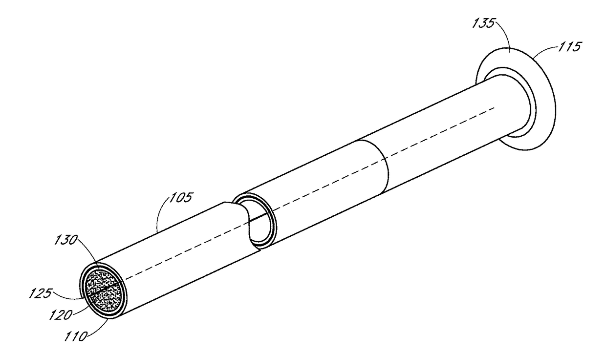
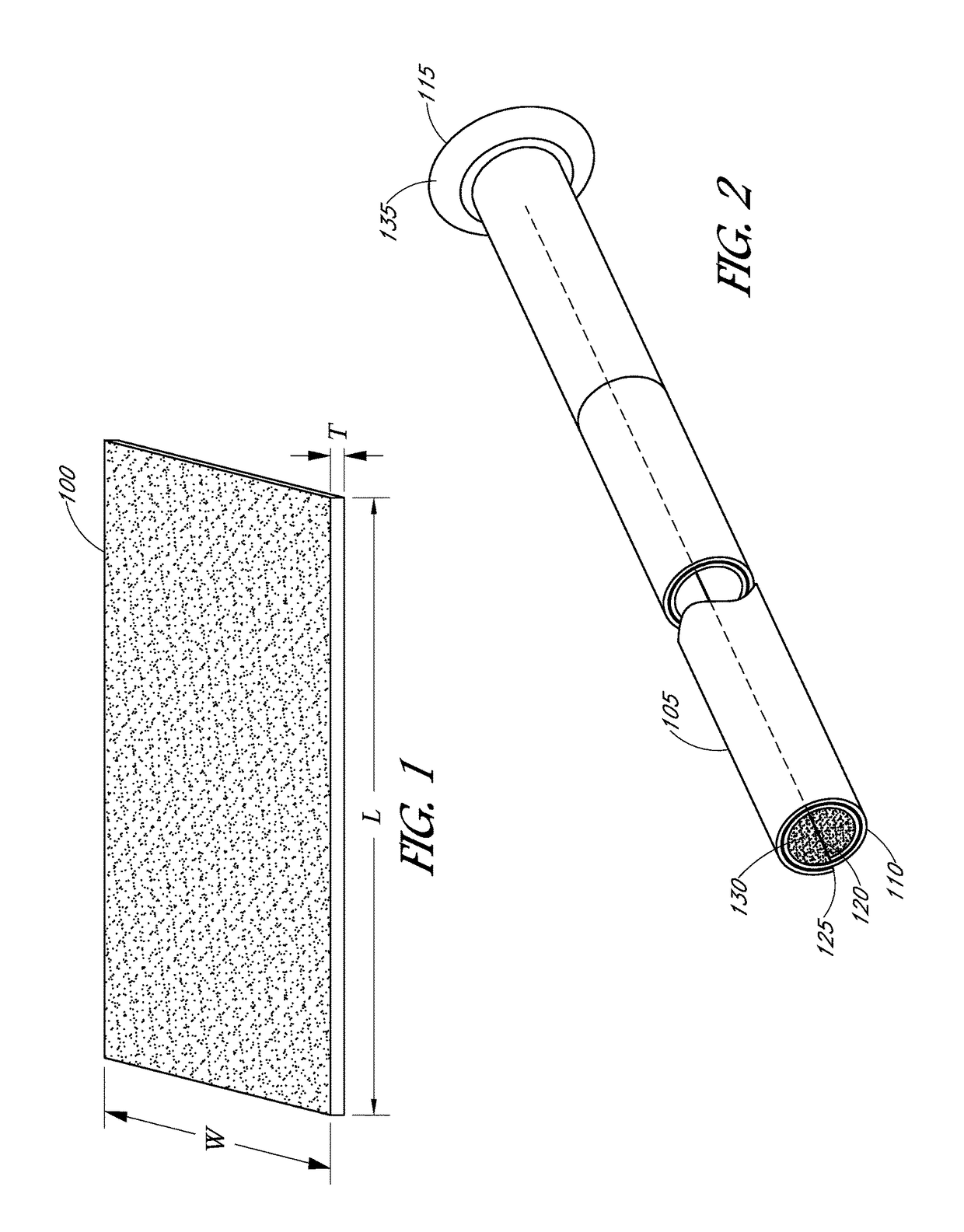
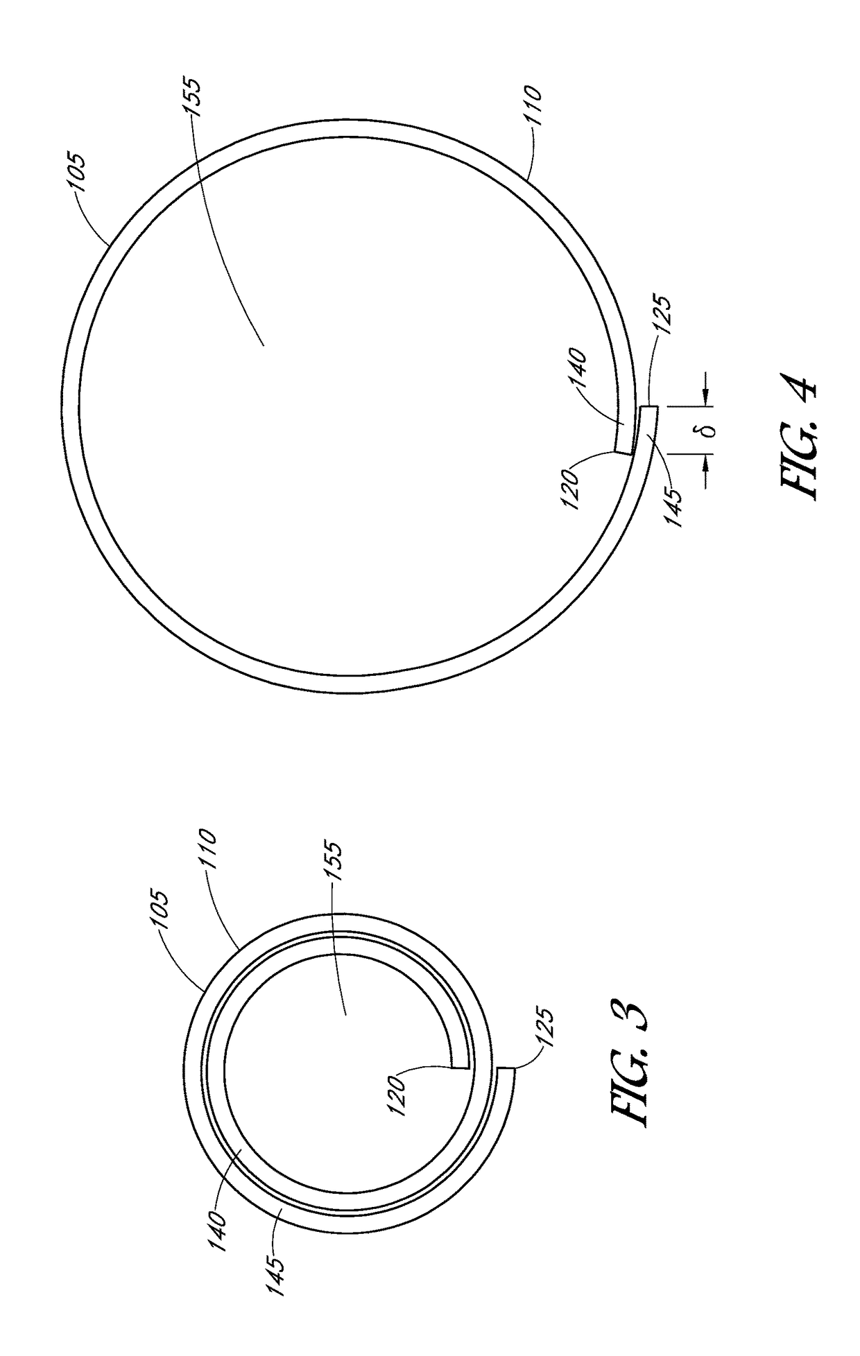
[0051]In some embodiments, an expandable sheath can be made of a rolled shaft from a sheet, such as a rectangular sheet in some cases. The sheet can be flat or substantially flat, and / or include macro or micro surface features, e.g., ridges, wells, and / or microstructures in some embodiments. In some embodiments, an expandable flat-sheet-rolled-shaft low profile sheath has an expandable flat-sheet-rolled-shaft design that can b...


PUM

PropertyMeasurementUnit
Forceaaaaaaaaaa
Pressureaaaaaaaaaa
Diameteraaaaaaaaaa

Abstract

Disclosed herein are expandable introducer sheaths and methods of making and using the same. The sheaths minimize trauma to a patient's vasculature by allowing for temporary expansion of a portion of the sheath state after passage of the device. The sheath includes a rolled inner member having a detachable flap structure at its distal tip that facilitates expansion of the sheath lumen to increase diameters. Also, the flap structure reduces the number of layers at the tip, lowering push forces. An elastomeric free end of the tip helps reduce push and retrieval forces for balloons and implants. The expandable sheath includes an elastic outer layer that compresses the inner member and flap back into the rolled, compressed condition after the passage of the device.

Description

INCORPORATION BY REFERENCE TO ANY PRIORITY APPLICATIONS[0001]Any and all applications for which a foreign or domestic priority claim is identified in the Application Data Sheet as filed with the present application are hereby incorporated by reference under 37 CFR 1.57. This application claims priority benefit of U.S. Provisional Application No. 62 / 375,141, filed Aug. 15, 2016, the entirety of which is hereby incorporated by reference herein.BACKGROUNDField of the Invention[0002]The present application relates in some aspects to embodiments of a sheath for use with catheter-based technologies to deploy a prosthetic device, such as a heart valve or other implant, into the patent's vasculature.Description of the Related Art[0003]Endovascular delivery catheter assemblies are used to implant prosthetic devices, such as a prosthetic heart valve, at locations inside the body that are not readily accessible by surgery or where access without surgery is desirable. For example, mitral, tricu...

Claims


Application Information

Patent Timeline
IPC IPC(8): A61M25/01A61M25/00
CPCA61M25/0152A61M25/001A61M25/0108A61M25/0041A61M25/0045A61F2/2436A61M25/0074A61M25/0097A61M2025/0024A61M2025/0025A61M25/0158A61M25/005A61F2/2427A61M25/0009A61M25/0023
Inventor WONG, JAMES
Owner ADVANCED CARDIOLOGY ENG SOLUTIONS LLC
Learn More