Hydroelectric turbine system

a technology of hydroelectric turbines and turbine blades, which is applied in the direction of fluid couplings, positive displacement liquid engines, couplings, etc., can solve the problems of limited volumetric efficiency and increase in the rotation per minute (rpm) of the blades, so as to avoid or lessen the disadvantages

Active Publication Date: 2019-04-04
NAVARRO RICHARD M
View PDF30 Cites 6 Cited by
  • Summary
  • Abstract
  • Description
  • Claims
  • Application Information

AI Technical Summary

Benefits of technology

[0027]The pitchback waterwheel comprises a housing, waterwheel, shaft, electrical generator, primary and secondary separate water sources, weir, Venturi valve, and a negative pressure to facilitate lift of the blades. The purpose of the pitchback waterwheel is to use water that was formerly wasted in other designs as efficiently as possible to produce electricity.
[0029]Above the waterwheel the primary flow from the turbine spent water pipe enters the top of the housing. After entering the housing, the water encounters a weir positioned on the floor of the pipe just before an opening on the floor of the pipe leading to the pitchback wheel. The weir serves two purposes 1) to increase the velocity of the portion of the water flowing to the pitchback waterwheel; and 2) to increase the pressure on the water prior to a Venturi constriction. The Venturi constriction is located just past the opening on the floor of the pipe leading to the waterwheel and it reduces the lumen of the pipe such that the portion of the water flow that does not pass to the waterwheel passes through the constriction at increased pressure. The water forced through the Venturi valve is increased in velocity and is dropped down a separate channel on the backside of the waterwheel. Along the backside channel wall one-third of the way vertically downward from the top of the waterwheel, an elevation is created on the housing wall proximal to the waterwheel such that the elevation is closed at the top and open at the bottom to cause the water to pass by the opening but not to enter it. As the water from the Venturi passes downwardly over this elevation, it creates a negative pressure in the open end of the elevation. This negative pressure assists in the lift on the backside of the waterwheel thereby facilitating the rotation of the water wheel via the Bernoulli effect.
[0033]In the preferred embodiment of the passive hydroelectric system, the system comprises one or more active hydroelectric systems housed on a floatation device such as a ship or barge. In this embodiment, however, a vertical siphon pipe and vector siphon pipe comprise a siphon mechanism to serve as the water source rather than flowing water from a low-head dam used in the active water system. In the preferred embodiment, a plurality of siphon mechanisms, hydrams, and hydroelectric turbines with associated housing are all located on a barge or ship. Assuming there is sufficient water from a given source, the plurality of siphon mechanisms allows for adjusting the amount of water being delivered to a given turbine. Within a hydroelectric system, the amount of electricity produced is the result of the inter-active action of the total head and the total amount of water delivered to the turbine.
[0035]The vertical siphon pipe and vector siphon drive pipe are hollow tubular members and comprise a siphon mechanism to lift the water from the passive water source. In a preferred embodiment, each active water system uses eight respective siphon mechanisms for each primary generator. However, a greater or lesser number of siphon mechanisms may be used. The sum of the total number of siphon mechanisms for each individual system contribute to the total amount of water ultimately flowing to the primary turbine. The velocity head from each siphon system is increased by the active water system previously described and used to increase the rotational speed of the turbine.
[0042]In some embodiments, the lower opening of the vertical siphon pipe may be coupled to a flexible section to ensure that it is always below the surface of the water yet higher than the lowest opening of the vector drive pipe to insure continuous operation of the siphon mechanism. The turbine may be located higher than the surface of the water source as the hydraulic ram has lifted the water to the turbine. The higher elevation will facilitate the exiting water to flow downward to the secondary turbine and to be re-deposited into the source via the tertiary flow previously described.

Problems solved by technology

Pumping efficiency ranges from 60-80% but volumetric efficiency is limited by the ratio of the source head to a discharge head.
Increased water pressure results in an increase in the revolutions per minute (rpm) of the blades.

Method used


Image

  • Hydroelectric turbine system
  • Hydroelectric turbine system
  • Hydroelectric turbine system

Examples


first embodiment

the Active Water Hydroelectric System

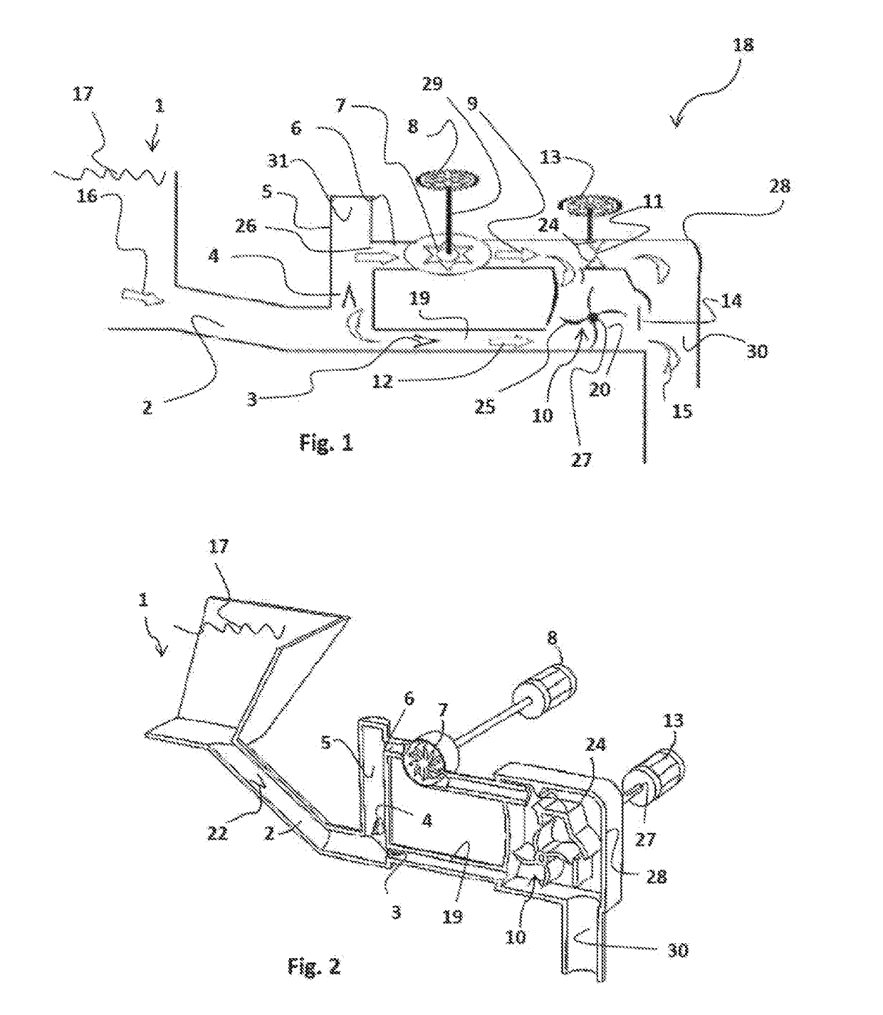
[0055]FIG. 1 depicts the components of the active water hydroelectric system 18 in accordance with a first embodiment. Generally, the system 18 comprises a housing 28 comprising a drive pipe 2 and a delivery pipe 6. The drive pipe 2 is fluidly coupled to the low head water source 1 comprising water 16. The drive pipe 2 is fluidly connected to a pressure vessel 6 comprising a bolus of air. A delivery valve 4 controls flow of water 16 from the drive pipe 2 to the pressure vessel 5. Water 16 entering the pressure vessel 6 exits the pressure vessel 5 into the delivery pipe 6. Water 16 exiting the pressure vessel 5 forms a primary flow 9. An impulse valve 3 positioned within the drive pipe 2 controls a secondary flow 12 of water 16.

[0056]The primary flow 9 of water 16 is elevated with respect to the secondary flow 12 of water 16. The primary flow 9 moves across a turbine 7 which turns a first generator 8. After exiting the turbine 7 a portion of the p...

second embodiment

the Active Water Hydroelectric System

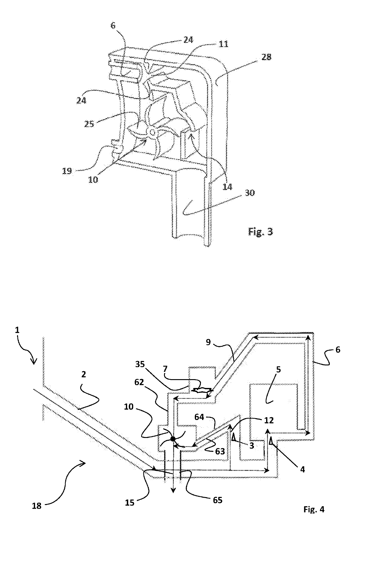
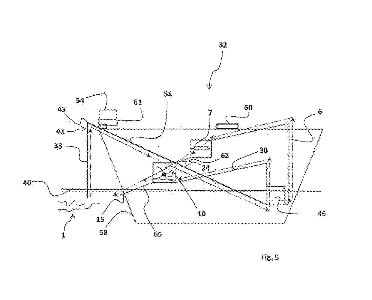
[0071]Referring to FIG. 4, there is shown the components of the active water hydroelectric system 18 in accordance with a second embodiment. Generally, the system 18 of this embodiment comprises the housing 28, drive pipe 2, impulse valve 3, delivery valve 4, pressure vessel 5, delivery pipe 6, and hydroelectric turbine 7 with first generator 8. The drive pipe 2 is fluidly coupled to the low head water source 1 comprising water 16 on one end passing through a water source control valve 22 to control the flow of water 16 from the drive pipe 2. On the other end, the water 16 is fluidly coupled to the drive impulse valve 3 (‘impulse valve’) and pressure vessel delivery valve 4 (‘delivery valve’) located below the pressure vessel 5 to create the hydram 46. In the hydram 46, the impulse and delivery valves 3, 4 serve as logic gates as they alternately start and stop the flow of water 16 to trigger the hammer effect. The active water hydroelectric syst...


PUM


Abstract

The active water hydroelectric system uses a hydraulic ram pump to increase pressure to turbine blades using water from a low head water source, the system comprising a housing, drive pipe, delivery pipe, pressure vessel, turbine, waterwheel, and first and second generators. The drive pipe is fluidly coupled to the low head water source and pressure vessel. A primary flow moves across a turbine turning a first generator. Primary and secondary flows turn the waterwheel which turns the second generator. The passive hydroelectric system a floatation device such as a ship or barge. A vertical siphon pipe and vector siphon pipe comprise a siphon mechanism that delivers water to the hydraulic ram pump. A primary flow of water flows from the pump to a drive pipe to the turbine. Primary and secondary flows of water turn the waterwheel. Water exits through an exit pipe.

Description

[0001]This application claims the benefit of provisional application Ser. No. 62 / 433,380 filed Dec. 13, 2016, and provisional application Ser. No. 62 / 554,674 filed Sep. 6, 2017 the contents of which are incorporated by reference herein in their entirety.FIELD OF THE INVENTION[0002]This disclosure relates generally to a hydroelectric turbine system and specifically to a hydroelectric turbine system comprising a hydraulic ram, the system being adapted for use in both passive and active water environments.BACKGROUND OF THE INVENTION[0003]Hydroelectric power is the most cost efficient form of renewable energy and is considered a mature industry as there have been few innovations in many years. Hydraulic rams (“hydrams”) have been used for hundreds of years to pump water without an external source of energy. The principles of hydraulic rams will be used to amplify the source head thereby improving the energy output of the turbine through increased rotational speed. Instead of pumping the...

Claims


Application Information

Patent Timeline
Patent Type & Authority Applications(United States)
IPC IPC(8): F03B13/08
CPCF03B13/086F03B17/04F05B2260/406F05B2260/42F03B13/00F03B17/005F05B2240/93F04B17/00Y02E10/20Y02E10/30Y02E60/16F16D31/02
Inventor NAVARRO, RICHARD M.
Owner NAVARRO RICHARD M
Why Eureka
Try Eureka