Deformable mount for LED assembly

a technology of led assembly and mount, which is applied in the direction of instruments, planar/plate-like light guides, mechanical instruments, etc., can solve the problems of high cost easy scratching of acrylic, etc., and achieve the effect of sufficient density and opacity, and greatest amount of luminosity

Active Publication Date: 2019-06-25
ADVANCED TECH
View PDF35 Cites 0 Cited by
  • Summary
  • Abstract
  • Description
  • Claims
  • Application Information

AI Technical Summary

Benefits of technology

[0014]The aforesaid and other objectives are realized by providing a multilayered illuminated laminate system including a pivotable aluminum clamp mount that attaches the system to a white mounting substrate such as a wall and houses a twenty-four inch (24″) long LED light source approximately three-sixteenths of an inch (0.188″) thick, defining six (6) diodes per lineal inch and producing about forty (40) lumens of illumination per inch. The light source on a single twenty-four volt (24 v) transformer is affixed to a lateral edge of an acrylic panel defining the same thickness as the light source and illuminating the face of the panel up to sixteen feet (16′) without a perceptible reduction in lumens. On the planar, horizontal surface most proximate the mounting substrate, a series of diamond shapes are digitally printed with a predetermined orientation relative to other diamonds that is maintained as the size of the diamond increases as the location of the diamond moves gradually further away from the light source. A partially opaque diffuser sheet is attached to the opposing horizontal panel surface to hide the diamond pattern from view and increase overall luminance. The diffuser sheet planar surface opposite the surface attached to the panel defines a printed graphic or pattern in translucent ink to increase the aesthetic appearance of the system which can be changed as desired by an owner. A translucent fiber reinforced panel layer is positioned atop the diffuser sheet to ensure that the laminate is impact, abrasion, and chemical resistant.

Problems solved by technology

However, the granite in these systems may be considered heavy, expensive, and susceptible to scratching, abrasion, and chemicals.
Unfortunately, the acrylic is also susceptible to scratching, abrasion, and chemical treatment, and thus is unsuitable for counter tops, backsplashes, table tops, bar tops, modesty panels, and the like.
A further issue with the illuminated substrates known in the prior art is that they nearly all require a panel of predefined dimensions, often contained within a mount or frame that cannot be significantly altered, least the emitted illuminative properties of the substrate be altered.
This presents a significant disadvantage for installers of these substrates, who routinely encounter errors in measurement, outlet location, and hardware position to name a few.
Still other substrates include the light source (usually an LED light source) mounted within a channel frame, further complicating installation and replacement.

Method used


Image

  • Deformable mount for LED assembly
  • Deformable mount for LED assembly
  • Deformable mount for LED assembly

Examples


Embodiment Construction

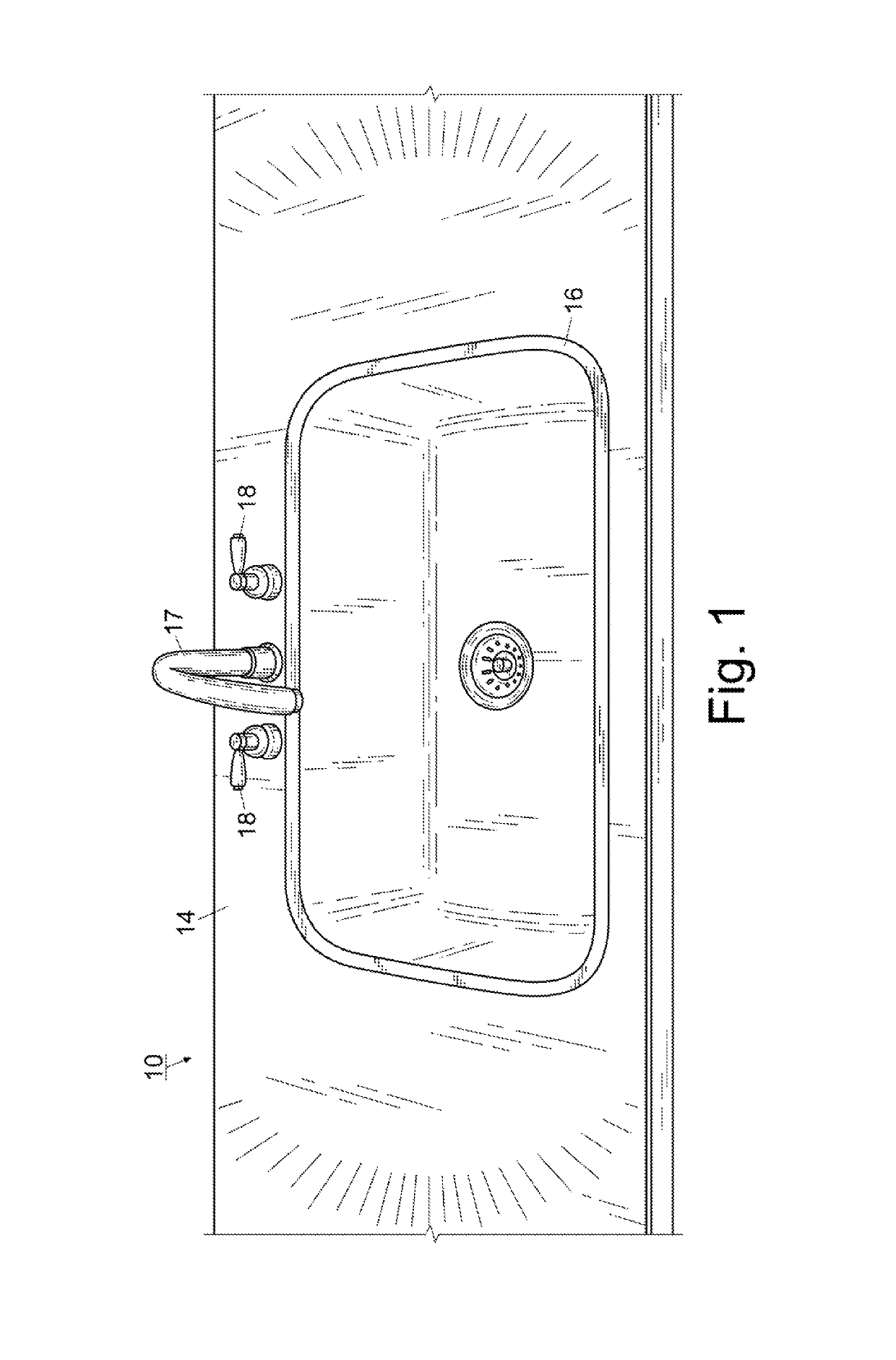
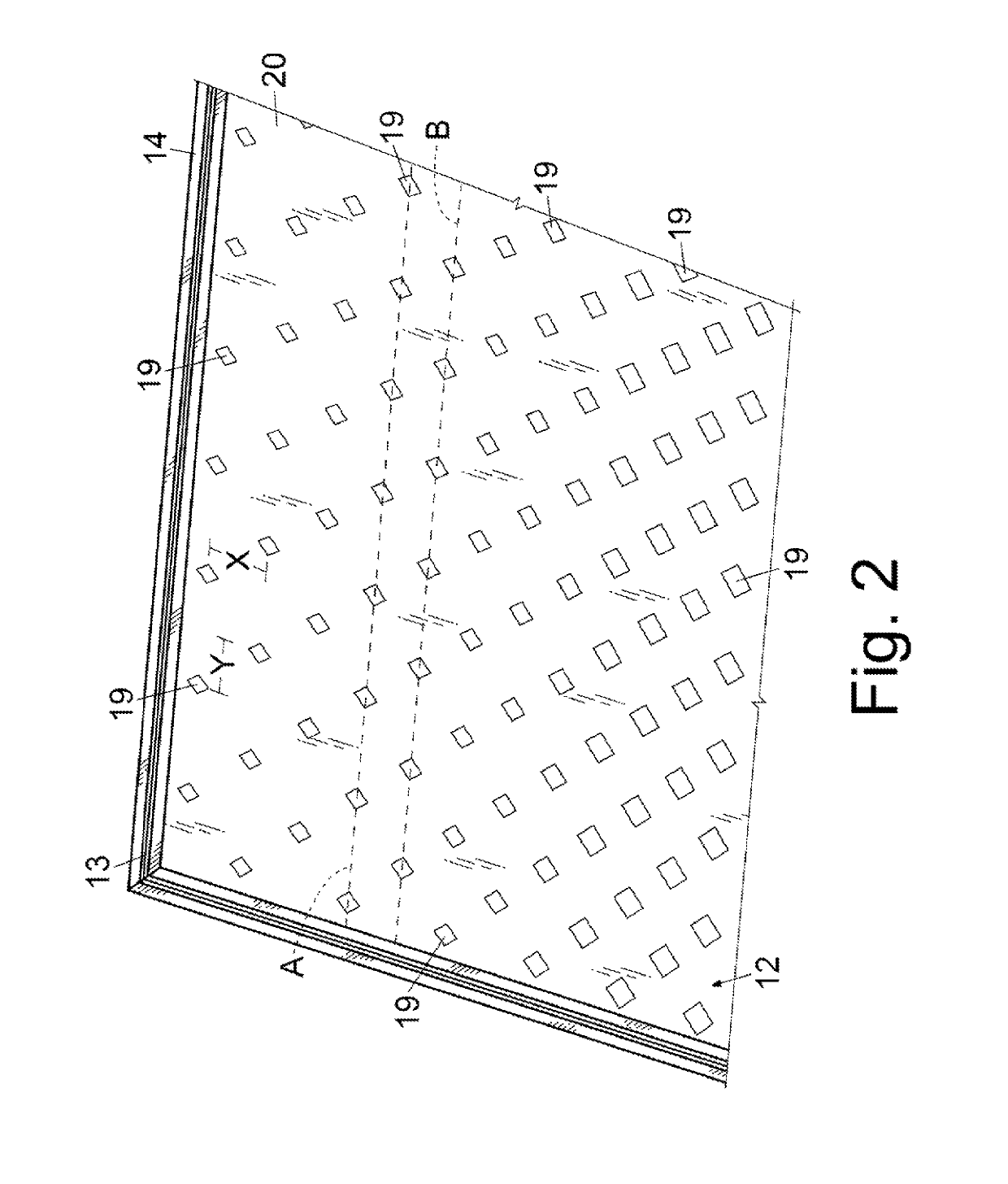
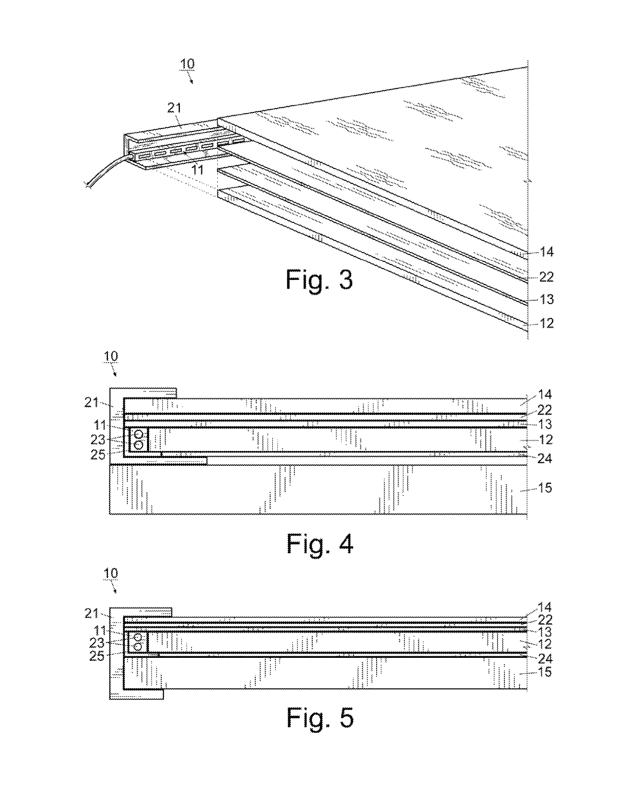
[0023]For a better understanding of the invention and its operation, turning now to the drawings, FIGS. 1-4 represent the preferred embodiment of multilayered illuminated laminate system 10 formed by light source 11 mounted to light panel 12, diffuser sheet 13, and reinforced panel 14. As will be described in further detail below, laminate system 10 can be applied directly to wall board, medium density fiberboard (MDF), plywood, drywall, or other preferred mounting substrates 15 without creating a void or gap either vertically or horizontally therebetween. Although not required, it may be preferable to include heat sink material 24 beneath light panel 12 to dissipate heat buildup emanating therefrom. If such a material causes a void between laminate system 10 and mounting substrate 15, such void can be filled with spacing shims, or substrate 15 can be routed out slightly (for example, about 0.020″) to accommodate the bottom portion of clamp mount 21. An embodiment of laminate system...


PUM

PropertyMeasurementUnit
widthaaaaaaaaaa
thickaaaaaaaaaa
thicknessaaaaaaaaaa

Abstract

A multilayered illuminated laminate system including a light source positioned proximate to an edge of a light panel that includes a series of reflective paint in the shape of diamonds of increasing size is provided. The system further includes a diffuser sheet of sufficient opacity that it obscures the diamond pattern on the bottom surface of the light panel and a reinforced panel formed from fiberglass that bestows the system with scratch, abrasion, impact, and chemical resistance to meet or exceed current regulatory requirements. The light source is positioned within a clamp mount that contains the light panel, diffuser, and reinforced panel in frictional engagement without the need for an adhesive. A graphic can be positioned between the diffuser sheet and the reinforced panel to increase the aesthetic appearance of the system exterior surface, as well as moderate the intensity of the light it emits.

Description

[0001]This is a continuation-in-part of and claims benefits under pending prior application Ser. No. 14 / 750,487 filed 25 Jun. 2015, now U.S. Pat. No. 10,101,521 which is incorporated by reference in its entirety herein.FIELD OF THE INVENTION[0002]The invention herein pertains to illuminated substrates and particularly pertains to multilayer laminate that utilizes a light guide carrying a plurality of digitally printed diamonds to uniformly reflect the edge lighting and emit luminescence along the entire face of the top surface.DESCRIPTION OF THE PRIOR ART AND OBJECTIVES OF THE INVENTION[0003]Edge lit illumination systems with a light source positioned abuttingly or in close proximity to a light transmitting surface or sheet are known in the art (see for example European Patent No. 0549679 or U.S. Pat. No. 6,568,821). The prior art is replete with examples of mechanisms and methods to light one or more substrates that are sufficiently translucent to permit light from behind or aside ...

Claims


Application Information

Patent Timeline
Patent Type & Authority Patents(United States)
IPC IPC(8): F16B2/24G09F13/18F21V8/00F16B5/06G02F1/1335
CPCG02B6/0091G02B6/0055G02B6/0051G02B6/0085G02B6/0095F16B2/245F16B5/0642F16B5/0635G02F1/133615G09F2013/1804F16B11/006G09F23/00
Inventor BURGIO, JR., JAMES G.
Owner ADVANCED TECH
Why Eureka
Try Eureka