Hydroelectric turbine system
a technology of hydroelectric turbines and turbine blades, which is applied in the direction of fluid couplings, positive displacement liquid engines, couplings, etc., can solve the problems of limited volumetric efficiency and increase in the rotation per minute (rpm) of the blades, so as to avoid or lessen the disadvantages
- Summary
- Abstract
- Description
- Claims
- Application Information
AI Technical Summary
Benefits of technology
Problems solved by technology
Method used
Image
Examples
first embodiment
[0055]the Active Water Hydroelectric System
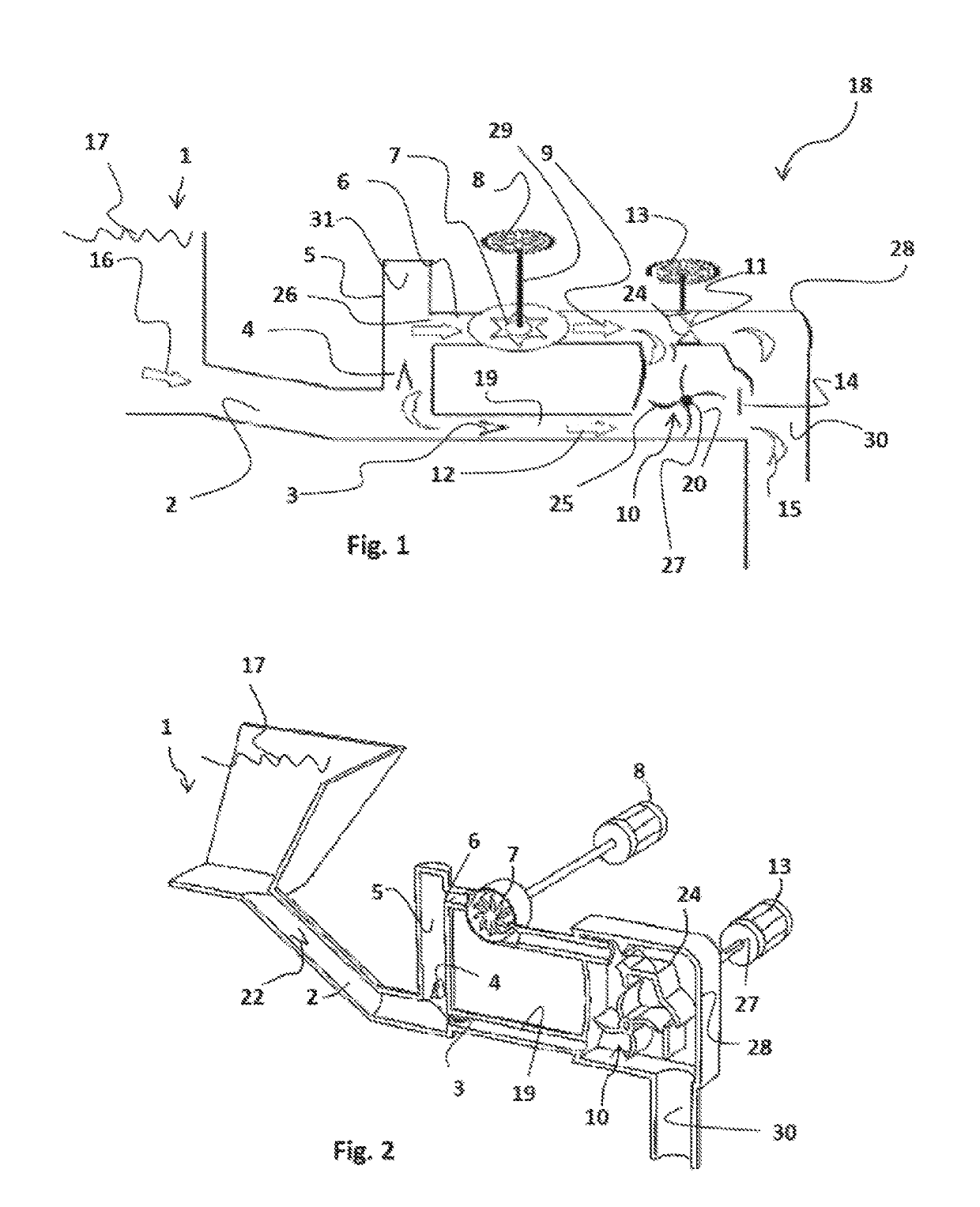
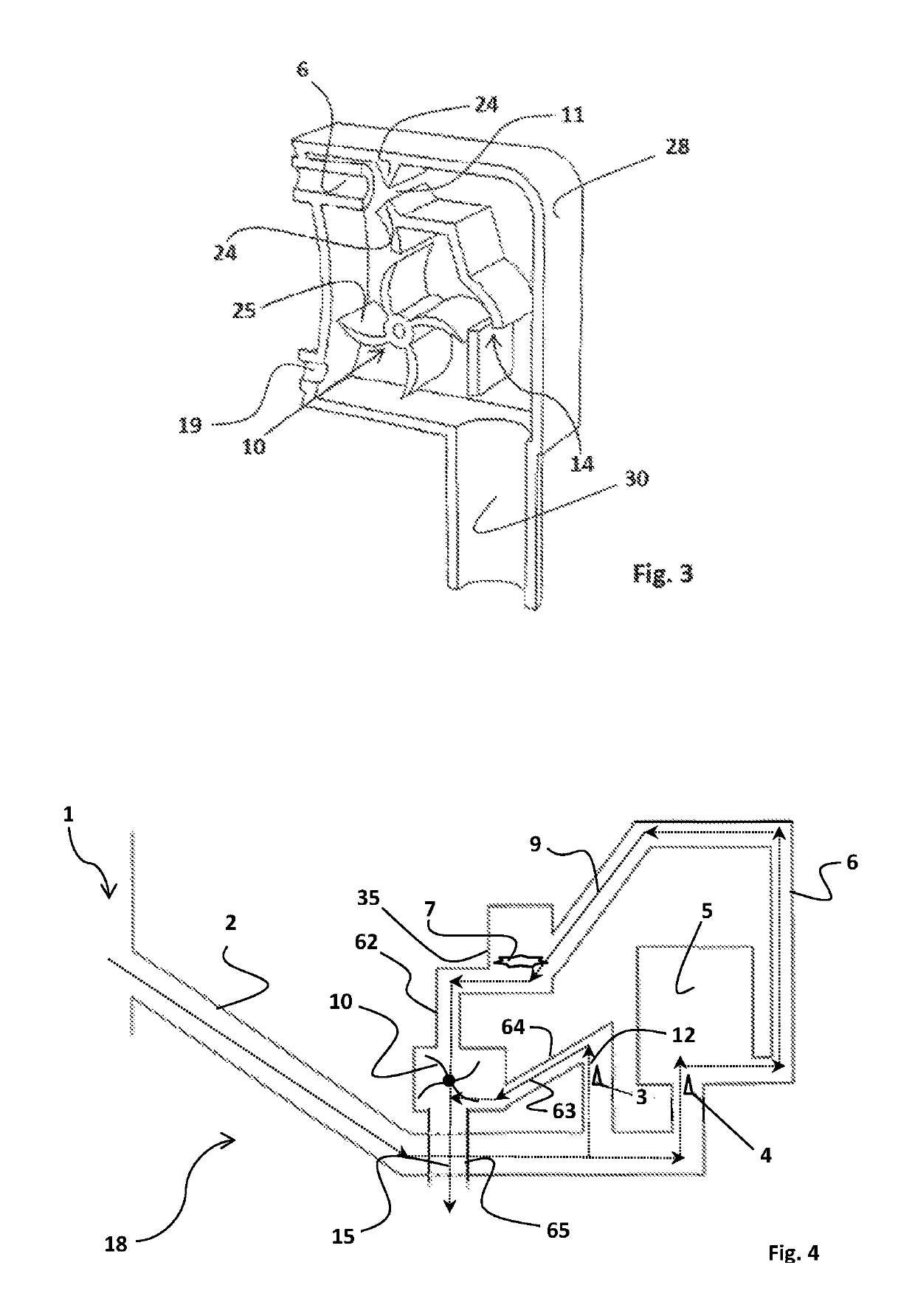
[0056]FIG. 1 depicts the components of the active water hydroelectric system 18 in accordance with a first embodiment. Generally, the system 18 comprises a housing 28 comprising a drive pipe 2 and a delivery pipe 6. The drive pipe 2 is fluidly coupled to the low head water source 1 comprising water 16. The drive pipe 2 is fluidly connected to a pressure vessel 6 comprising a bolus of air. A delivery valve 4 controls flow of water 16 from the drive pipe 2 to the pressure vessel 5. Water 16 entering the pressure vessel 6 exits the pressure vessel 5 into the delivery pipe 6. Water 16 exiting the pressure vessel 5 forms a primary flow 9. An impulse valve 3 positioned within the drive pipe 2 controls a secondary flow 12 of water 16.
[0057]The primary flow 9 of water 16 is elevated with respect to the secondary flow 12 of water 16. The primary flow 9 moves across a turbine 7 which turns a first generator 8. After exiting the turbine 7 a portion of...
second embodiment
[0072]the Active Water Hydroelectric System
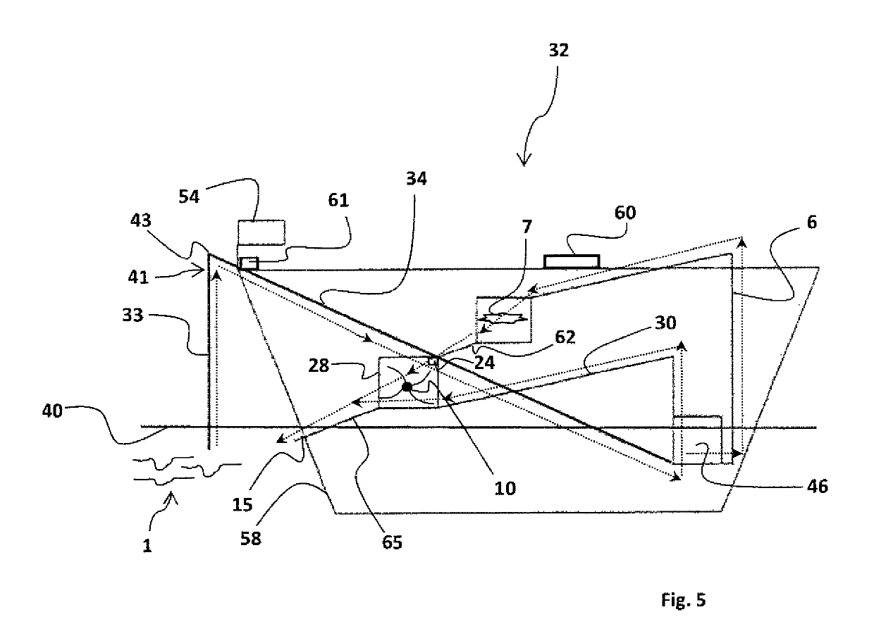
[0073]Referring to FIG. 4, there is shown the components of the active water hydroelectric system 18 in accordance with a second embodiment. Generally, the system 18 of this embodiment comprises the housing 28, drive pipe 2, impulse valve 3, delivery valve 4, pressure vessel 5, delivery pipe 6, and hydroelectric turbine 7 with first generator 8. The drive pipe 2 is fluidly coupled to the low head water source 1 comprising water 16 on one end passing through a water source control valve 22 to control the flow of water 16 from the drive pipe 2. On the other end, the water 16 is fluidly coupled to the drive impulse valve 3 (‘impulse valve’) and pressure vessel delivery valve 4 (‘delivery valve’) located below the pressure vessel 5 to create the hydram 46. In the hydram 46, the impulse and delivery valves 3, 4 serve as logic gates as they alternately start and stop the flow of water 16 to trigger the hammer effect. The active water hydroelectri...
PUM
 Abstract
Description
Claims
Application Information
 - R&D
- Intellectual Property
- Life Sciences
- Materials
- Tech Scout
- Unparalleled Data Quality
- Higher Quality Content
- 60% Fewer Hallucinations
Browse by: Latest US Patents, China's latest patents, Technical Efficacy Thesaurus, Application Domain, Technology Topic, Popular Technical Reports.
© 2025 PatSnap. All rights reserved.Legal|Privacy policy|Modern Slavery Act Transparency Statement|Sitemap|About US| Contact US: help@patsnap.com


