Transfer system with a pushing device for piece objects

Active Publication Date: 2018-02-15
WRH WALTER REIST HLDG
View PDF2 Cites 10 Cited by
  • Summary
  • Abstract
  • Description
  • Claims
  • Application Information

AI Technical Summary

Benefits of technology

[0081]A device with which only translatory movements are effected in the pushing movement is accordingly designed in a simple and robust manner.
[0082]The second piece object can be reliably and securely positioned in the conveying region due to the braking of t

Problems solved by technology

With each pushing procedure, the known pushers are at risk of pushing the piece object which is to be transferred to the conveyor, into a piece object, which is already located on the conveyor.
Here, the piece o

Method used


Image

  • Transfer system with a pushing device for piece objects
  • Transfer system with a pushing device for piece objects
  • Transfer system with a pushing device for piece objects

Examples


Example

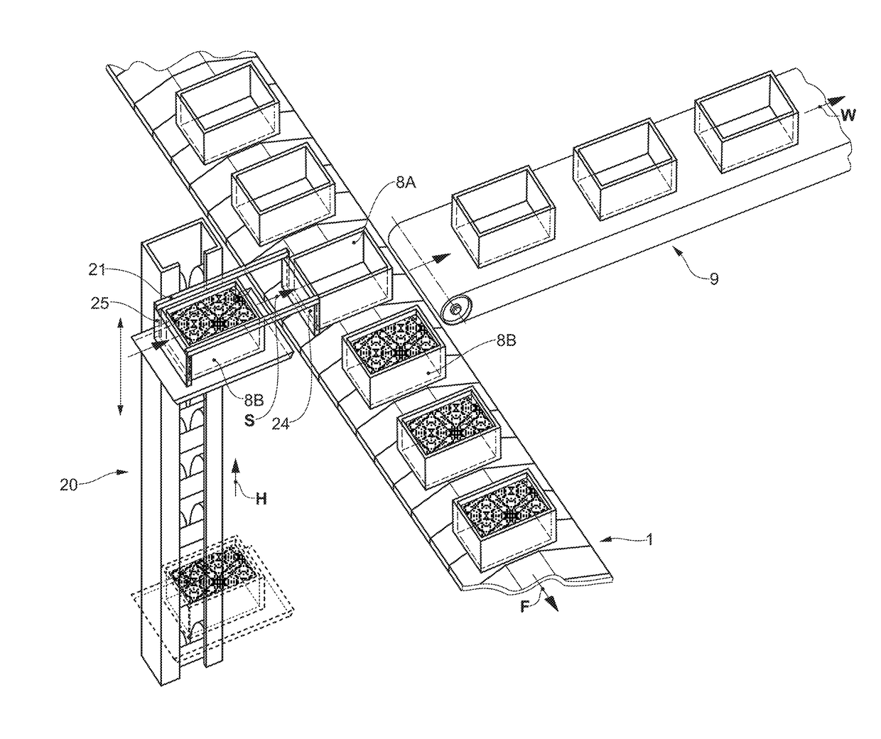
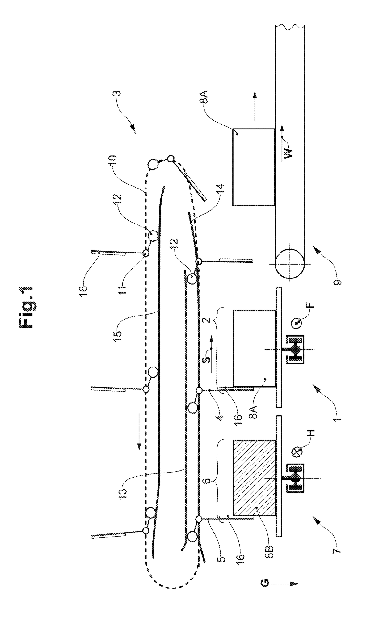
[0109]FIG. 1 shows a first embodiment of a transfer system with a first pushing device 3. The gravitational direction, which in FIG. 1 points downwards, thus onto the lower edge of FIG. 1 is indicated with G. The main conveyor 1 is a plate chain conveyor, whose conveying direction F is led out perpendicularly to the plane of the drawing towards the viewer. A plate chain conveyor includes plates that are fastened on a conveying chain and on which piece objects can be conveyed. A conveying region 2 is formed on the main conveyor 1. The conveying region 2 is delimited to the bottom by a rest surface of the conveyor 1 and extends laterally almost up to the lateral ends of the rest surface of the main conveyor 1. A piece object 8a, 8b, which is arranged in the conveying region 2 of the main conveyor 1, is held on the main conveyor 1 by way of static friction. The static friction of the piece object 8A, 8B on the main conveyor 1 arises due to the pressing force on account of the weight fo...

Example

[0118]A second embodiment of a transfer system with a second pushing device 23 is represented in FIG. 2, as in FIG. 1 likewise after the beginning of a pushing movement. FIG. 2 as FIG. 1 likewise only represents a detail of the complete transfer system. The second embodiment of the transfer system in FIG. 2 differs from the first embodiment of the transfer system in FIG. 1 by a differently designed pushing device 23 and by a different supply of the supply zone 6.

[0119]The supply zone 6 in FIG. 2 is supplied by a lift 20 instead of by an incoming conveyor 7 as in FIG. 1. Here, the lift 20 moves full piece objects 8B from the bottom to the top into the supply zone 6. Once the full piece object 8B has been transferred from the second pushing member 25 onto the main conveyor 1 by the pushing movement, the lift 20 moves downwards again, in order to fetch a further full piece object 8B and to bring this upwards again into the supply zone 6.

[0120]The pushing device 23 in the second embodim...


PUM


Abstract

A transfer system for piece objects includes a pushing device and a main conveyor with a conveying region. The pushing device includes first and second pushing members. The transfer system includes a supply zone, which is behind the conveying region in a pushing direction. In an initial position of the pushing device, the first pushing member is between the conveying region and the supply zone and the second pushing member is behind the supply zone in the pushing direction. In an end position of the pushing device, the first pushing member is in front of the conveying region in the pushing direction and the second pushing member is between the conveying region and the supply zone. The first pushing member, between the initial position and the end position, is at a fixed spacing to, and in front, of the second pushing member in the pushing direction.

Description

BACKGROUND OF THE INVENTIONField of the Invention[0001]The invention relates to the field of transfer systems with a pushing device for the transfer of piece objects onto a conveyor, as well as to the field of methods for the transfer of piece objects onto a conveyor by a pushing device.Description of Related Art[0002]Amongst other things, conveyors are used for conveying piece objects. The transfer of piece objects onto the conveyor in order to convey them with the conveyor over a predefined stretch is a commonly known procedure. Various devices and systems already exist for this. Pushing procedures and pushing devices for the transfer onto the conveyor are widespread in the case that the piece object is connected to the conveyor essentially by way of static friction and thus by way of a pressing force upon the conveyor. Here, pushers are used and these transfer the piece object onto the conveyor by way of the piece object being pushed onto the conveying surface of the conveyor. Su...

Claims


Application Information

Patent Timeline
IPC IPC(8): B65G47/84B65G47/53B65G47/82B65G43/08
CPCB65G47/844B65G43/08B65G2203/0208B65G47/82B65G47/53B65G47/32B65G47/71B65G47/841
Inventor MADER, CARL CONRAD
Owner WRH WALTER REIST HLDG
Why Eureka
Try Eureka