Illumination device

a technology of illumination device and illumination device, which is applied in the direction of lighting and heating apparatus, using reradiation, instruments, etc., can solve the problems of large illumination device and large volume of sensor for acquiring information outside the vehicle based on invisible light, and achieve the effect of suppressing an increase in the size of the illumination devi

Active Publication Date: 2018-02-15
KOITO MFG CO LTD
View PDF2 Cites 18 Cited by
  • Summary
  • Abstract
  • Description
  • Claims
  • Application Information

AI Technical Summary

Benefits of technology

[0006]Exemplary embodiments of the invention provide an illumination device which can suppress an increase in size of the illumination device while providing a sensor for acquiring information outside a vehicle based on invisible light.

Problems solved by technology

However, it is general that the sensor for acquiring information outside the vehicle based on invisible light has a relatively large volume.
Thus, the illumination device tends to be large.

Method used


Image

  • Illumination device
  • Illumination device
  • Illumination device

Examples


Embodiment Construction

[0029]Hereinafter, an example of an embodiment according to the present invention will be described in detail with reference to the accompanying drawings. In each drawing used in the following description, the scale is appropriately changed in order to make each member recognizable size.

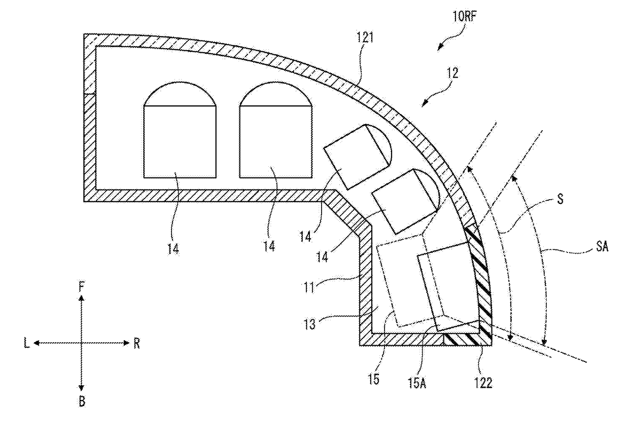
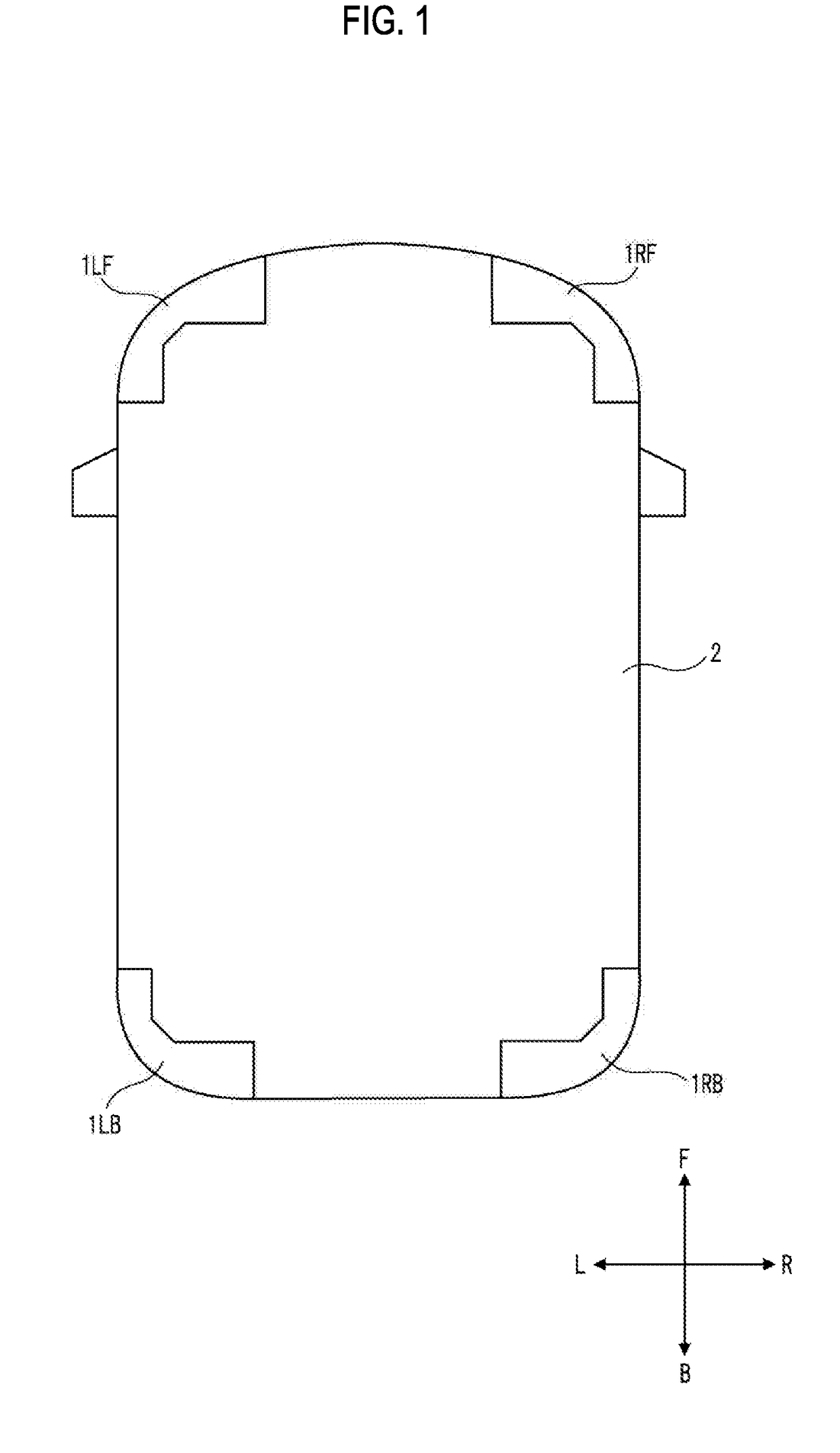
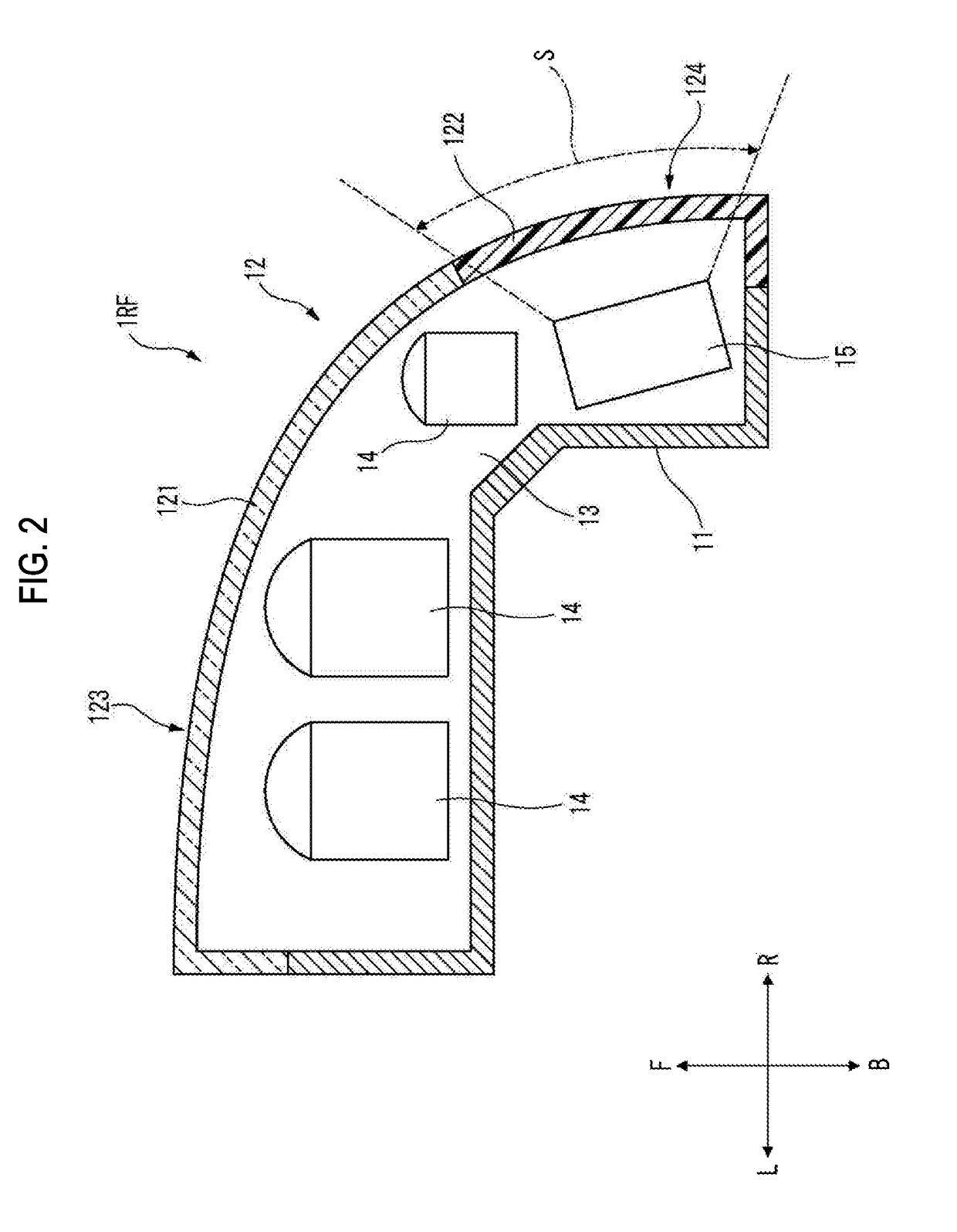
[0030]In the accompanying drawings, the arrow F indicates a forward direction of a structure shown, the arrow B indicates a rearward direction of a structure shown, the arrow U indicates an upward direction of a structure shown, the arrow D indicates a downward direction of a structure shown, the arrow L indicates a leftward direction of a structure shown, and the arrow R indicates a rightward direction of a structure shown. The “left” and the “right” used in the following description indicate the left and right directions as viewed from a driver's seat.

[0031]As shown in FIG. 1, a left front illumination device 1LF according to an embodiment is mounted on a left front corner portion of a vehicle 2, a...


PUM


Abstract

An illumination device to be mounted on a vehicle, includes a light source; a sensor configured to acquire information outside the vehicle based on invisible light; and a cover including a first portion covering the light source and a second portion covering the sensor. The second portion has a lower visible light transmittance than the first portion.

Description

CROSS-REFERENCE TO RELATED APPLICATION[0001]The present application claims priority from Japanese Patent Application No. 2016-158727 filed on Aug. 12, 2016, the entire content of which is incorporated herein by reference.BACKGROUNDTechnical Field[0002]The present invention relates to an illumination device mounted on a vehicle.Related Art[0003]In order to realize an automatic driving technique of a vehicle, it is necessary to mount a sensor for acquiring information outside the vehicle on a vehicle body. A LiDAR (Light Detection and Ranging) is known as an example of such a sensor (e.g., see Patent Document 1). The LiDAR sensor is a device for emitting invisible light and acquiring information on the distance to an object or the attribute of an object based on the reflected light.[0004]Patent Document 1: Japanese Patent Laid-Open Publication No. 2010-185769[0005]From the viewpoint of efficiently acquiring information around the vehicle and from the viewpoint of design, it is desired...

Claims


Application Information

Patent Timeline
Patent Type & Authority Applications(United States)
IPC IPC(8): G01S17/02B60Q1/30G01S17/88B60Q1/00F21V23/04B60Q1/04G01S17/86G01S17/931
CPCG01S17/023F21V23/0457B60Q1/0483B60R2011/0094B60Q1/0023B60Q1/302G01S7/4972G01S17/88F21V23/0442G01S17/42G01S7/4813G01S17/931G01S17/86
Inventor KASABA, YUSUKEHORI, TAKASHIYAMAMOTO, TERUAKI
Owner KOITO MFG CO LTD
Why Eureka
Try Eureka