Front Light Unit and Image Display Device
Active Publication Date: 2018-02-15
LG INNOTEK CO LTD
View PDF3 Cites 7 Cited by
- Summary
- Abstract
- Description
- Claims
- Application Information
AI Technical Summary
Benefits of technology
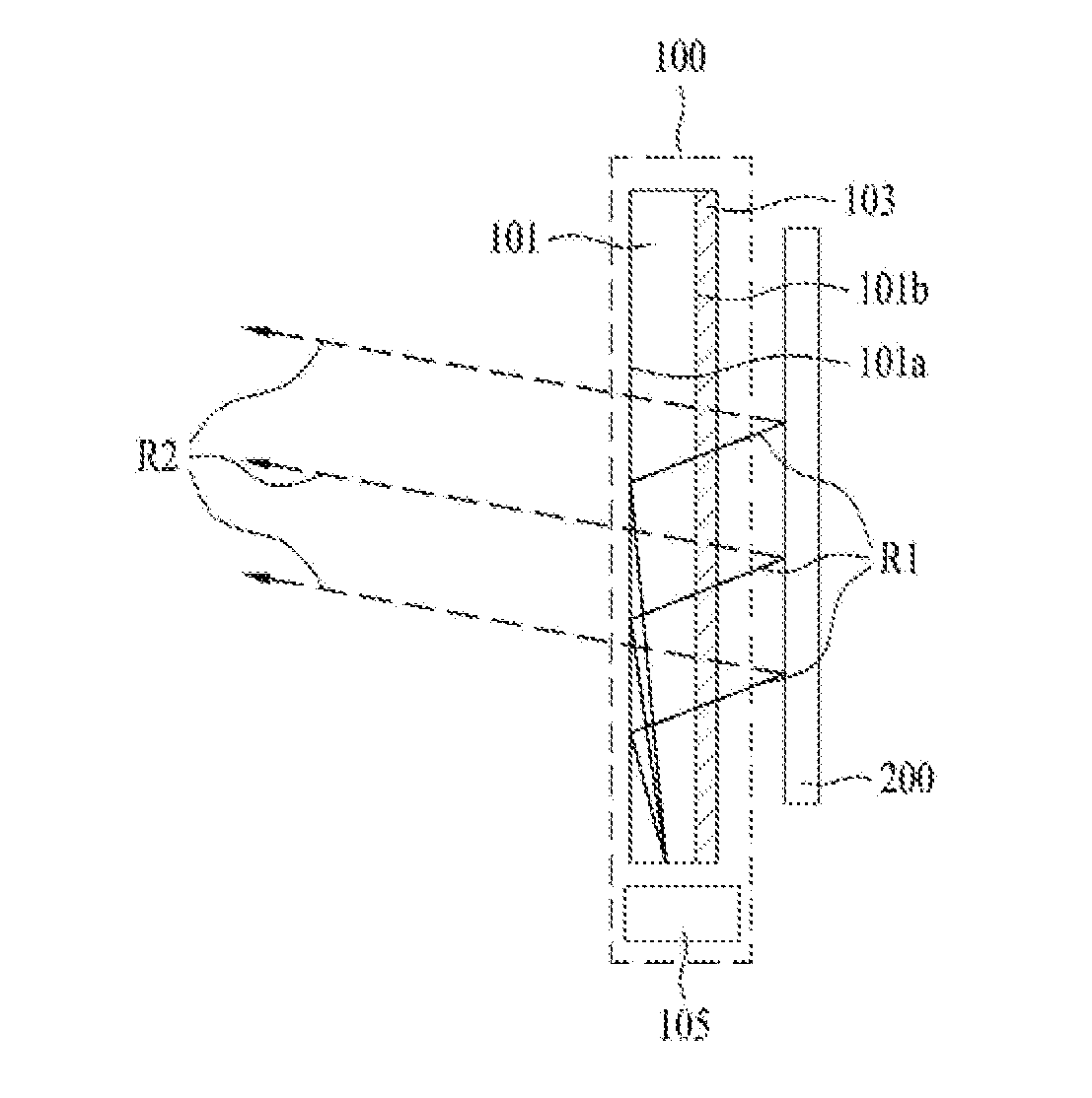
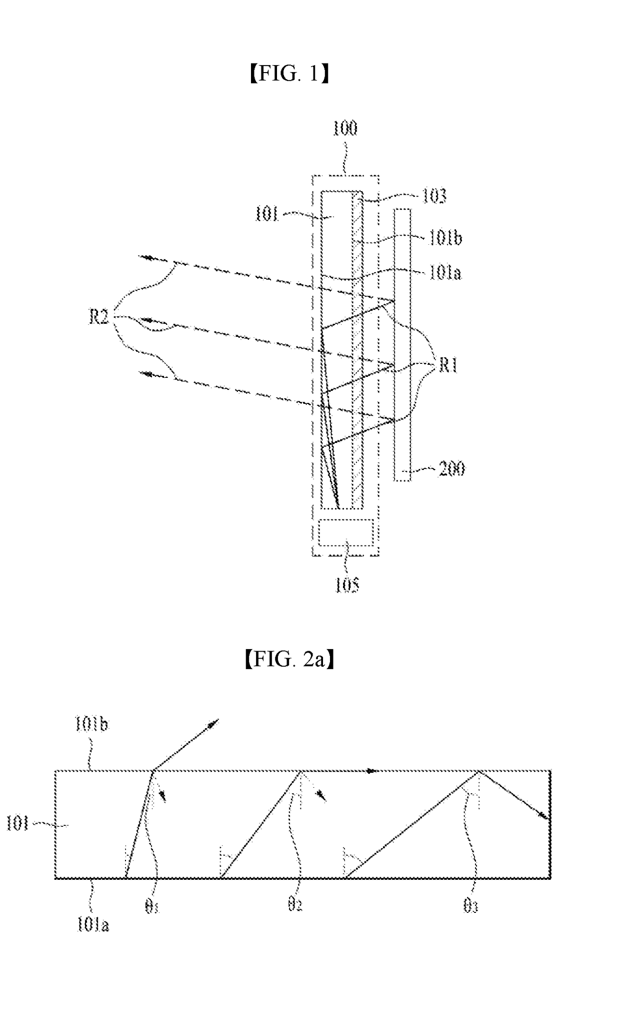
The front light unit described in this patent can adjust the direction of light that is sent to a display using a special optical element. This improves the efficiency of the light and reduces the size of the light unit and the display device. It also allows for a larger image to be displayed using a special prism.
Problems solved by technology
However, there is a problem in that the polarization beam splitter is an expensive optical component and in that there is a limitation in the extent to which the size of the image display device can be reduced due to the space occupied by the polarization beam splitter.
Method used
View moreImage
Smart ImageViewing Examples
Examples
Embodiment Construction
[0189]Various embodiments have been described in the best mode for carrying out the invention.
INDUSTRIAL APPLICABILITY
[0190]An image display device according to the embodiment is capable of adjusting the direction of light that is transferred to a display unit, thereby minimizing light loss, improving light efficiency, and greatly reducing the size of an image display device.
Login to View More PUM
 Abstract
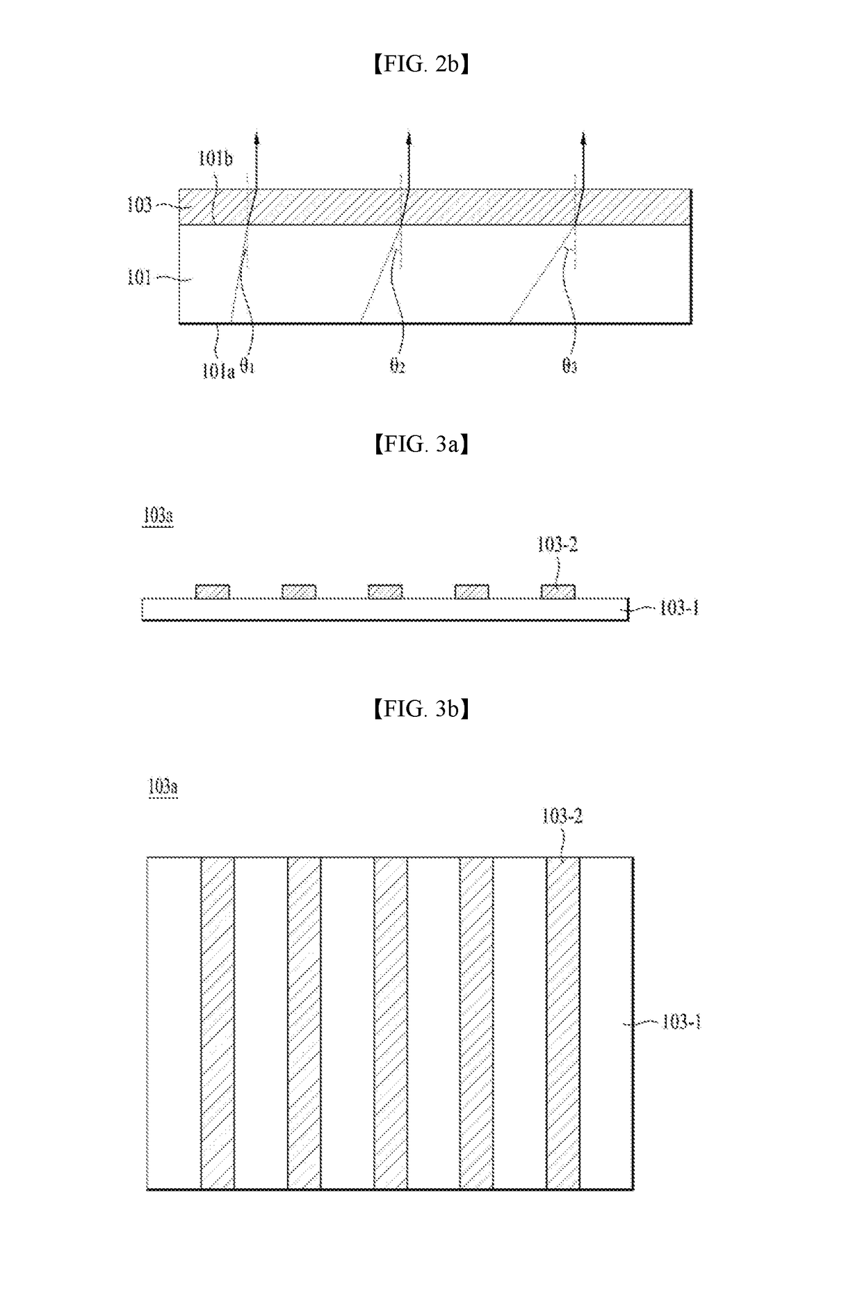
A front light unit of an embodiment comprises: a light source unit for an image display device; a light guide unit for guiding light incident from the light source unit and outputting the guided light to a display unit; and a holographic optical element unit being opposite to the display unit and disposed on the light guide unit. Therefore, the present invention can adjust the direction of light output from the light source unit and increase the quantity of light transferred to the display unit, using a pattern formed in the holographical optical element unit, thereby improving the efficiency of light supplied from the light source unit and reducing the sizes of the light unit and the display device including the same.
Description
TECHNICAL FIELD[0001]Embodiments relate to a front light unit and an image display device.BACKGROUND ART[0002]An image display device, which converts an image generated and supplied from a display device, such as a liquid crystal (LC) display device or an electro luminescence (EL) display device, into a virtual image using a virtual image optical system and supplies the same to an observer, is commonly known.[0003]Such an image display device is being applied to recently widely used wearable display devices such as, for example, head-mounted displays (HMDs), smart glasses, etc.[0004]Further, the image display device is also being applied to head-up display devices, which display a virtual image indicating various information necessary for traveling to a point on a sight line of a pilot or a driver so that the virtual image is overlaid on the field of view ahead of the pilot or the driver.[0005]A conventional image display device employs a polarization beam splitter in order to trans...
Claims
Login to View More Application Information
Patent Timeline
 IPC IPC(8): G02B6/42F21V8/00G02B6/28G02B6/34G02F1/1335G02B5/32G02B6/27
CPCG02B6/4204G02B5/32G02B6/0023G02B6/27G02B6/34G02B6/0031G02F1/133615G02B6/2817G02B27/01G02B27/0103G02B2027/0174G02B2027/015G02B2027/0118G02B27/0172G02B6/005G02F1/136281
Inventor LEE, SANG HUNKIM, MINKIM, TAE KYUNGJANG, JUNG IN
Owner LG INNOTEK CO LTD
Features
- R&D
- Intellectual Property
- Life Sciences
- Materials
- Tech Scout
- Unparalleled Data Quality
- Higher Quality Content
- 60% Fewer Hallucinations
Learn More Browse by: Latest US Patents, China's latest patents, Technical Efficacy Thesaurus, Application Domain, Technology Topic, Popular Technical Reports.
© 2025 PatSnap. All rights reserved.Legal|Privacy policy|Modern Slavery Act Transparency Statement|Sitemap|About US| Contact US: help@patsnap.com


