Autonomous driving system

Active Publication Date: 2018-02-15
TOYOTA JIDOSHA KK
View PDF1 Cites 17 Cited by
  • Summary
  • Abstract
  • Description
  • Claims
  • Application Information

AI Technical Summary

Benefits of technology

[0010]The lane selection section may be configured to determine the threshold density in accordance with at least a forward inter-vehicle distance between the own vehicle and a vehicle traveling ahead of the own vehicle in the lane on which the own vehicle is traveling, or a rearward inter-vehicle distance between the own vehicle and a vehicle traveling behind the own vehicle in the lane on which the own vehicle is traveling. According to this configuration, whether to perform lane change to the adjacent lane is determined with a congestion state in the lane on which the own vehicle is traveling also taken into consideration, in addition to the vehicle density in the adjacent lane. Consequently, an effect of lane change of the own vehicle dispersing a traffic flow can be enhanced, and lane change to suit to a sense of an occupant can be realized. In this case, the threshold density may be set at a smaller value as the forward inter-vehicle distance or the rearward inter-vehicle distance is long.
[0011]The lane selection section may be configured to determine the threshold density in accordance with at least a vehicle density in a lane on which the own vehicle is traveling. According to this configuration, whether to perform lane change to the adjacent lane is determined with a congestion state in the lane on which the own vehicle is traveling also taken into consideration, in addition to the vehicle density in the adjacent lane. Consequently, an effect of lane change of the own vehicle dispersing a traffic flow can be enhanced, and lane change to suit to a sense of an occupant can be realized. In this case, the threshold density may be set at a smaller value as a vehicle density in the lane on which the own vehicle is traveling is small.
[0012]Further, the lane selection section may be configured to select as the own vehicle travel lane a lane having a lower vehicle density, of both adjacent lanes that are adjacent to a lane on which the own vehicle is traveling, when vehicle densities in both the adjacent lanes are lower than the threshol

Problems solved by technology

Therefore, an imbalance in a traffic flow c

Method used


Image

  • Autonomous driving system
  • Autonomous driving system
  • Autonomous driving system

Examples


first embodiment

1-1. Configuration of Autonomous Driving Vehicle

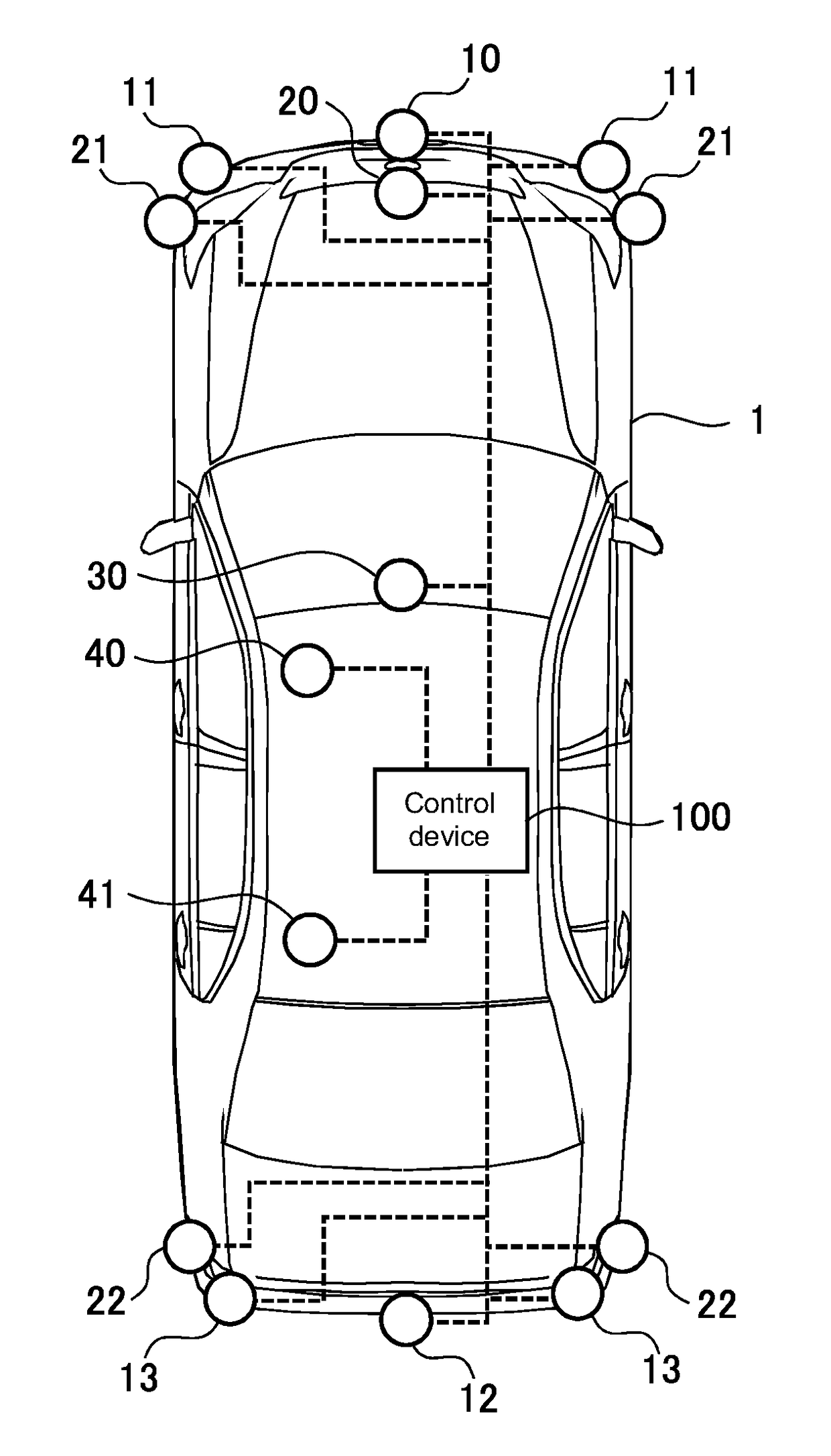
[0028]FIG. 1 is a view illustrating an example of an autonomous driving vehicle on which an autonomous driving system according to a first embodiment is mounted. The autonomous driving system performs autonomous driving of a vehicle on which the system is mounted. Note that autonomous driving means that driving operations such as acceleration, deceleration and steering of a vehicle is executed without a driving operation of a driver.

[0029]As illustrated in FIG. 1, a vehicle 1 mounted on the autonomous driving system includes an autonomous recognition sensor for directly acquiring information concerning a road on which the vehicle 1 is traveling and information concerning objects that are present in the surroundings of the vehicle 1. The autonomous recognition sensor includes at least one of LIDARs (LIDAR: Laser Imaging Detection and Ranging) 10, 11, 12 and 13, radars 20, 21 and 22 and a camera 30. Further, the vehicle 1 includes a comm...

second embodiment

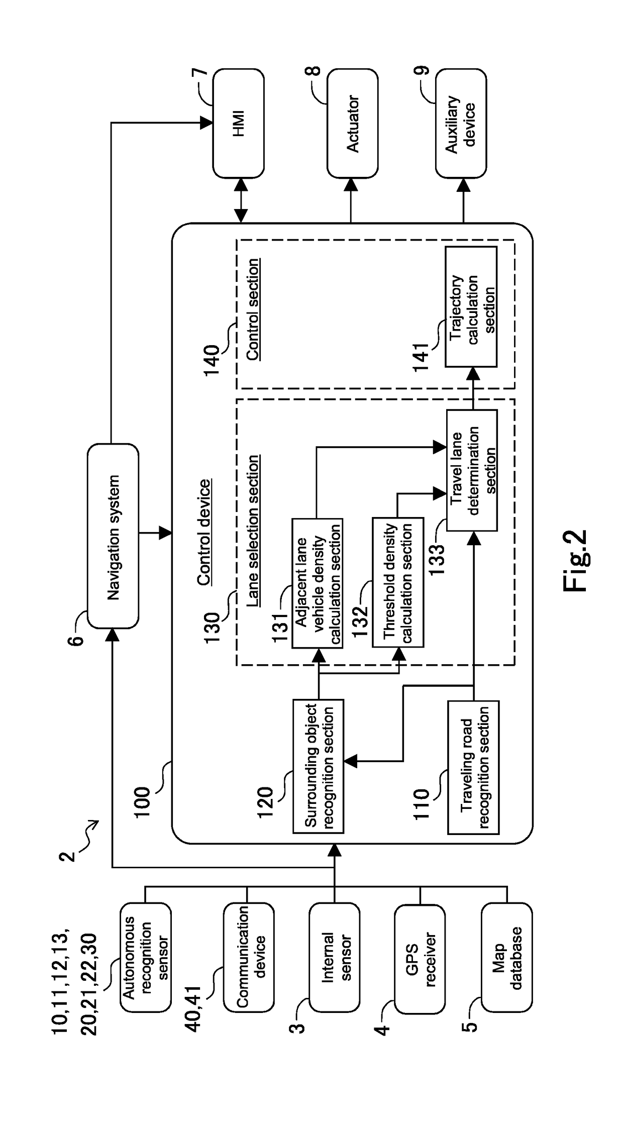
[0063]An autonomous driving system according to the present embodiment has the configuration illustrated in FIG. 2 as in the autonomous driving system according to the first embodiment, and is mounted on the autonomous driving vehicle illustrated in FIG. 1. A difference between the autonomous driving system according to the present embodiment and the autonomous driving system according to the first embodiment lies in the calculation method of the threshold density by the threshold density calculation section 132.

[0064]In the present embodiment, the threshold density calculation section 132 acquires a forward inter-vehicle distance between the own vehicle and the preceding vehicle that is included in the recognition information of surrounding objects. In an example illustrated in FIG. 3, a forward inter-vehicle distance between the own vehicle 1 and the preceding vehicle 201 traveling in the own lane L2 is acquired.

[0065]The threshold density calculation section 132 calculates a thre...

third embodiment

[0068]An autonomous driving system according to the present embodiment has the configuration illustrated in FIG. 2 as in the autonomous driving system according to the first embodiment, and is mounted on the autonomous driving vehicle illustrated inFIG. 1. A difference between the autonomous driving system according to the present embodiment and the autonomous driving system according to the first embodiment lies in the calculation method of the threshold density by the threshold density calculation section 132.

[0069]In the present embodiment, the threshold density calculation section 132 calculates the vehicle density in the own lane as the threshold density. As illustrated in FIG. 3, vehicles recognizable in the own vehicle travel lane L2 are only the preceding vehicle 201 and the following vehicle 202 in closest vicinities, and it is difficult to recognize the other vehicles because the other vehicles are in blind spots of the autonomous recognition sensors 10 to 13, 20 to 22 and...


PUM


Abstract

An autonomous driving system acquires information concerning a vehicle density in an adjacent lane that is adjacent to a lane on which an own vehicle is traveling, when the own vehicle travels on a road having a plurality of lanes. The autonomous driving system selects the adjacent lane as an own vehicle travel lane, when the vehicle density in the adjacent lane that is calculated from the acquired information is lower than a threshold density that is determined in accordance with relations between the own vehicle and surrounding vehicles. The autonomous driving system performs lane change to the adjacent lane autonomously, or propose lane change to the adjacent lane to a driver, when the adjacent lane is selected as the own vehicle travel lane.

Description

CROSS-REFERENCE TO RELATED APPLICATION[0001]This application claims priority to Japanese Patent Application No. 2016-157705, filed on Aug. 10, 2016, which is incorporated by reference herein in its entirety.BACKGROUNDField[0002]The present disclosure relates to an autonomous driving system mounted on a vehicle.Background Art[0003]DE 102012025328A1 discloses a device that determines whether or not to execute lane change based on vehicle speeds of and inter-vehicle distances of vehicles traveling in an adjacent lane when determining that a driver has an intention to perform lane change.SUMMARY[0004]For realizing smooth traffic, it is demanded not to generate an imbalance in a traffic flow in each of lanes.[0005]However, according to the prior art described in DE 102012025328A1, lane change is performed regardless of an imbalance in a traffic flow when lane change is demanded. Therefore, an imbalance in a traffic flow cannot be eliminated by using this prior art.[0006]The present discl...

Claims


Application Information

Patent Timeline
IPC IPC(8): G05D1/02B60W10/18B60W10/20B60W30/14B60W30/18
CPCG05D1/0223G05D1/0248G05D1/0276B60W30/143B60W30/18163B60W10/20B60W10/18B60W2420/42B60W2420/52B60W2520/14B60W2550/302B60W2550/306B60W2550/308B60W2520/10B60W2720/14B60W2720/10B60W2750/302B60W2750/306B60W2750/308G05D2201/0213B60W40/04B60W50/14B60W2552/05B60W2554/804B60W2554/00B60W2556/45B60W2050/0075B60W2554/801B60W2554/4041B60W2754/10B60W2754/30B60W2754/50B60W2552/50B60W2554/4026B60W2554/4029B60W2554/20B60W2554/802B60W2554/406B60W2420/403
Inventor HASHIMOTO, RYUTAWATANABE, YOSHINORIAOKI, KENICHIROKURIYAMA, TOMOYUKI
Owner TOYOTA JIDOSHA KK
Why Eureka
Try Eureka