Eureka AIR delivers breakthrough ideas for toughest innovation challenges, trusted by R&D personnel around the world.

Air conditioning apparatus

Active Publication Date: 2016-09-15
FUJITSU GENERAL LTD
View PDF4 Cites 11 Cited by
  • Summary
  • Abstract
  • Description
  • Claims
  • Application Information

AI Technical Summary

Benefits of technology

The present invention provides an air conditioning apparatus that solves the problem of unbalanced refrigerant oil between outdoor units at a low cost and with good workability. The apparatus allows surplus refrigerant oil to flow out of the unit with the excess oil being sent to the refrigerant circuit to reduce the oil imbalance. This avoids the need for costly oil equalizing pipes and improves the ease of installation.

Problems solved by technology

Since a refrigerant oil of the compressor is discharged from the compressor together with a refrigerant and flows through the refrigerant circuit, distribution of the refrigerant oil between the outdoor units may be unbalanced with variations in the refrigerant flow rate.
When such a state continues, a large amount of refrigerant oil may be unbalanced in the outdoor unit with a low number of rotations of the compressor.
In this case, the number of oil equalizing pipes according to the number of outdoor units installed is required, and there is a problem of increasing cost since the number of oil equalizing pipes is increased as the number of outdoor units installed is increased.
Also, when one outdoor unit of the plurality of outdoor units is installed in a place separate from another outdoor unit, the length or the shape of the oil equalizing pipe must be changed according to the installation place of the outdoor unit, and there is a problem of decreasing workability in the case of installing the air conditioning apparatus.

Method used


Image

  • Air conditioning apparatus
  • Air conditioning apparatus
  • Air conditioning apparatus

Examples


example

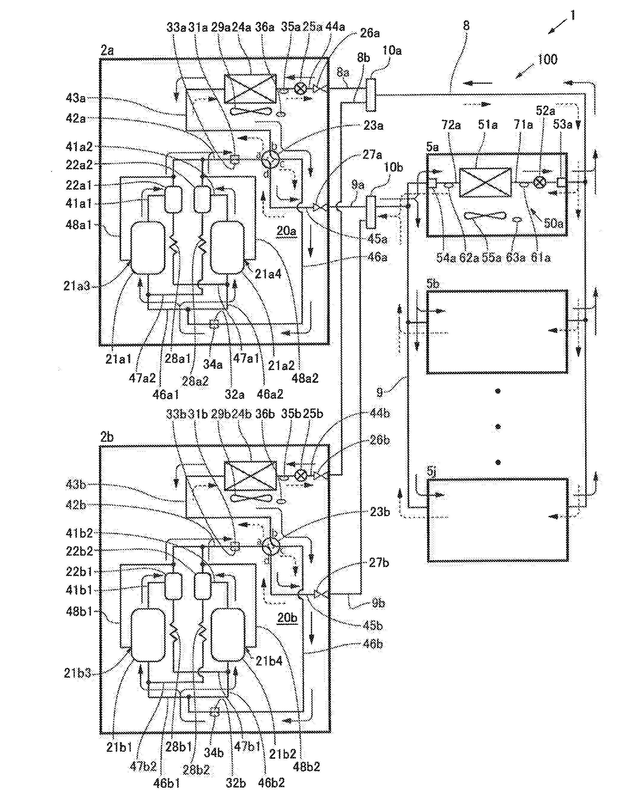
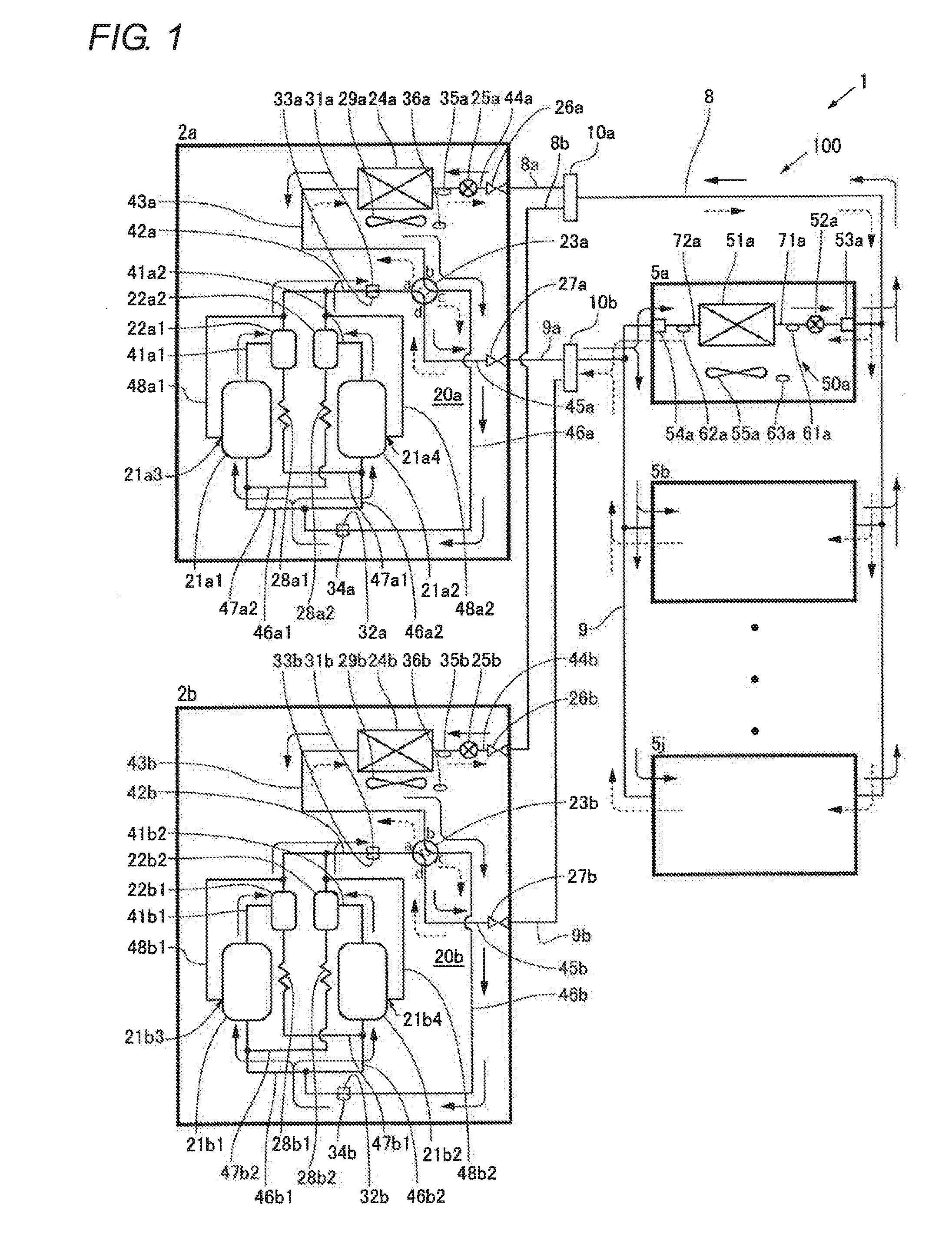
[0013]As shown in FIG. 1, an air conditioning apparatus 1 in the present embodiment includes two outdoor units 2a, 2b installed in the outside of a room, ten indoor units 5a to 5j connected to the outdoor units 2a, 2b by a liquid pipe 8 and a gas pipe 9, a liquid side branch device 10a, and a gas side branch device 10b. Specifically, one end of the liquid pipe 8 is connected to the liquid side branch device 10a, and the other end of the liquid pipe 8 is connected to each of liquid pipe connecting parts 53a to 53j of the indoor units 5a to 5j, respectively. A closing valve 26a of the outdoor unit 2a is connected to the liquid side branch device 10a by a liquid branch pipe 8a, and a closing valve 26b of the outdoor unit 2b is connected to the liquid side branch device 10a by a liquid branch pipe 8b, respectively. One end of the gas pipe 9 is connected to the gas side branch device 10b, and the other end of the gas pipe 9 is connected to each of gas pipe connecting parts 54a to 54j of ...


PUM


Abstract

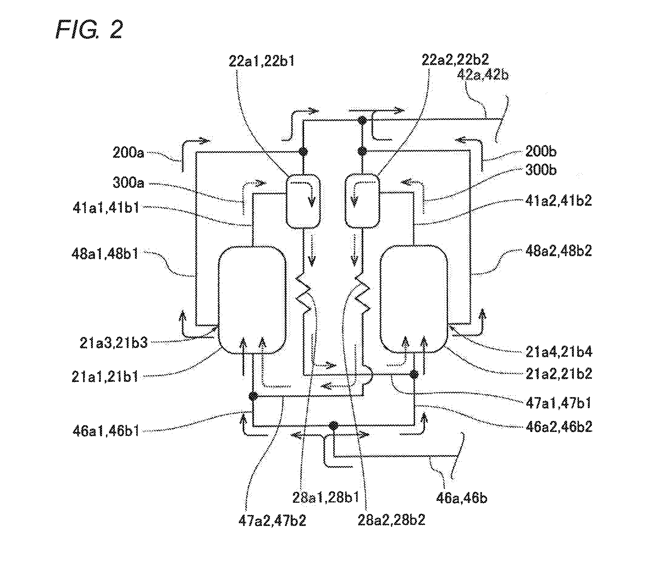
In an air conditioning apparatus, when the amounts of refrigerant oils retained in a first compressor and a second compressor are increased and oil levels in the first compressor and the second compressor reach a first oil outflow part and a second oil outflow part, the refrigerant oils subsequently sucked into the first compressor and the second compressor flow out of the first oil outflow part and the second oil outflow part to a first oil outflow pipe and a second oil outflow pipe, and flow from the first oil outflow pipe and the second oil outflow pipe to a refrigerant outflow pipe. The refrigerant oils flowing in the refrigerant outflow pipe from the first and second compressor through the first and second oil outflow pipe flow out of an outdoor unit through a four-way valve, and circulate through a refrigerant circuit together with refrigerants.

Description

CROSS-REFERENCE TO RELATED APPLICATION[0001]The present application claims the benefit of priority of Japanese Patent Application No. 2015-047641, filed on Mar. 10, 2015, which is incorporated herein by reference.TECHNICAL FIELD[0002]The present invention relates to an air conditioning apparatus, and particularly to the air conditioning apparatus including plurality of outdoor units.BACKGROUND[0003]An air conditioning apparatus for making connection between the plurality of outdoor units and the plurality of indoor units by refrigerant pipe is widely used conventionally. In such an air conditioning apparatus, a refrigerant flow rate in a refrigerant circuit varies greatly depending on, for example, a difference in the number of rotations of a compressor mounted in each of the outdoor units or the number of operations of the outdoor units. Since a refrigerant oil of the compressor is discharged from the compressor together with a refrigerant and flows through the refrigerant circuit,...

Claims


Application Information

Patent Timeline
IPC IPC(8): F25B31/00F24F1/68F25B43/02F25B13/00F25B41/04
CPCF25B43/02F24F1/68F25B41/046F25B13/00F25B31/004F24F1/08F24F1/28F24F13/02F25B2313/0253
Inventor KIMURA, TAKASHIMATSUNAGA, TAKAHIROSHIMOTANI, MAKOTO
Owner FUJITSU GENERAL LTD
Why Eureka
Eureka Blog
Learn More