Eureka AIR delivers breakthrough ideas for toughest innovation challenges, trusted by R&D personnel around the world.

Camera device and monitoring system

Inactive Publication Date: 2007-08-30
SONY SEMICON SOLUTIONS CORP
View PDF7 Cites 9 Cited by
  • Summary
  • Abstract
  • Description
  • Claims
  • Application Information

AI Technical Summary

Benefits of technology

[0009]In this case, when the cutout portions have large intervals therebetween, images are discontinuously shown on a display at a time of panning, tilting, zooming, or rotating. On the other hand, when the cutout portions have small intervals therebetween, images are comparatively successively shown on a display at a time of panning, tilting, zooming, or rotating. However, since the display of successive images should have many distortion correction parameters to be stored in a storage device, the capacity of the storage device should be increased, resulting in an increase in system cost.
[0010]To address these drawbacks, if a host computer generates the distortion correction parameters by performing calculation processing as needed instead of storing the distortion correction parameters in the storage device in advance, an increase in the capacity of the storage device is not necessary, resulting in smooth display of the images at the time of panning, tilting, zooming or rotating. However, if the host computer takes an excessive amount of time for calculation of the distortion correction parameters, the images are discontinuously shown on a display. Accordingly, an expensive host computer with high performance is necessary for reducing the calculation time. However, this leads to an increase in system cost.
[0012]Accordingly, it is desirable to provide a camera device in which the direction of a lens thereof is fixed and which is capable of smoothly displaying an image at the time of panning, tilting, zooming, or rotating and to provide a monitoring system utilizing the camera device without increasing the cost of the camera device or the system.
[0016]Since a camera device performs distortion correction for an image captured by the super-wide-angle lens, for example, the host computer to which the camera device is connected through a line, for example, merely have standard performance. A controller of the camera device merely indicates distortion correction parameters for a source image and distortion correction parameters for a final image to be obtained. Inexpensive distortion-correction-parameter interpolation means generates other necessary distortion correction parameters to perform distortion correction on an image. Accordingly, the cost of the monitoring system is not increased and smooth display of the image is achieved at the time of panning, tilting, zooming or rotating.
[0017]Furthermore, since the total number of pixels receiving light of the imaging element is larger, for example five to six times larger, than the total number of pixels of an image which is output from the camera device and to which the distortion correction has been applied, deterioration of an image after the distortion correction can be suppressed and the image having excellent quality can be obtained.
[0018]According to the embodiment of the present invention, since a camera device performs distortion correction for an image captured by the super-wide-angle lens, the host computer to which the camera device is connected through a line, for example, merely have standard performance. Accordingly, use of such a host computer does not lead to an excessive increase in the cost of the monitoring system. In the camera device, the controller (a microcomputer) merely indicates distortion correction parameters for a source image and distortion correction parameters for a final image to be obtained. The other necessary distortion correction parameters are generated by interpolation to thereby perform distortion correction on an image. Accordingly, smooth display of the image is achieved at the time of panning, tilting, zooming or rotating. Since the controller does not have many distortion correction parameters, a large-capacity storage apparatus or a high-performance central processing unit (CPU) is not necessary. Accordingly, use of such a camera device does not lead to an increase in the cost of the monitoring system. Furthermore, since the distortion-correction-parameter interpolation means may be constituted by inexpensive hardware, use of such distortion-correction-parameter interpolation means does not lead to an increase in the cost of the monitoring system. Accordingly, smooth operations such as panning, tilting, zooming, and rotating can be achieved with an inexpensive monitoring system. Since the advantages described above are obtained, a dome camera device (a camera in which the direction of a lens thereof is changed by mechanically driving the lens) used in the monitoring system is replaceable by a camera device in which the direction of a lens thereof is fixed. Furthermore, since the total number of pixels receiving light of the imaging element is larger, for example five to six times larger, than the total number of pixels of an image which is output from the camera device and to which the distortion correction has been applied, deterioration of an image after the distortion correction can be suppressed and the image having excellent quality can be obtained.

Problems solved by technology

In the above-described monitoring system in the related art, however, since an inexpensive host computer with low performance takes a significant amount of time to perform the image processing such as distortion correction, cutout processing, or compositing, the image processing is not terminated within one frame, resulting in deterioration of real-time processing.
In this case, however, system cost is increased.
Furthermore, since the total number of pixels of an imaging sensor mounted on the camera, the total number of pixels of a source image, and the total number of pixels of an image output from the camera are generally the same, a peripheral area of the image output from the camera has a low resolution due to distortion aberration characteristics of the lens.
Accordingly, when an analog transmitter (such as national television system committee (NTSC)) is used, the source image which is to be processed by the host computer is deteriorated by the time the host computer obtains the source image due to an adverse effect of transmission noise.
Therefore, even when the distortion of the deteriorated source image is corrected in the host computer, a high-quality image is not obtained.
However, since the display of successive images should have many distortion correction parameters to be stored in a storage device, the capacity of the storage device should be increased, resulting in an increase in system cost.

Method used


Image

  • Camera device and monitoring system
  • Camera device and monitoring system
  • Camera device and monitoring system

Examples


Embodiment Construction

[0034]Embodiments of the present invention will be described in detail hereinafter with reference to the accompanying drawings.

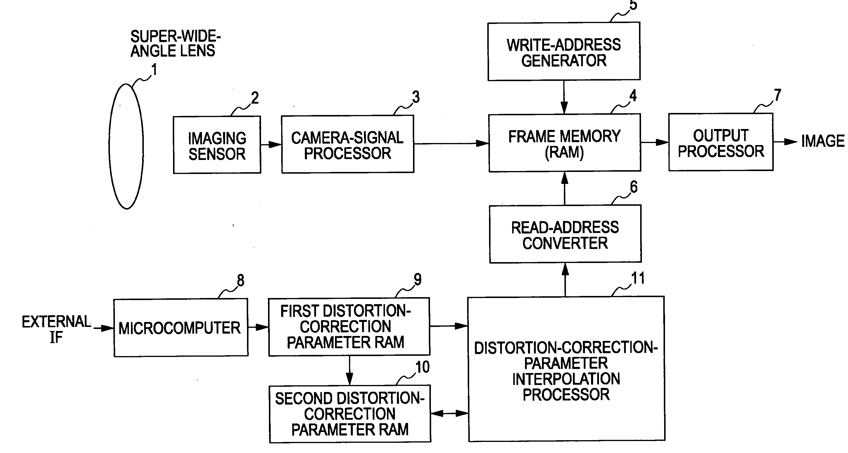
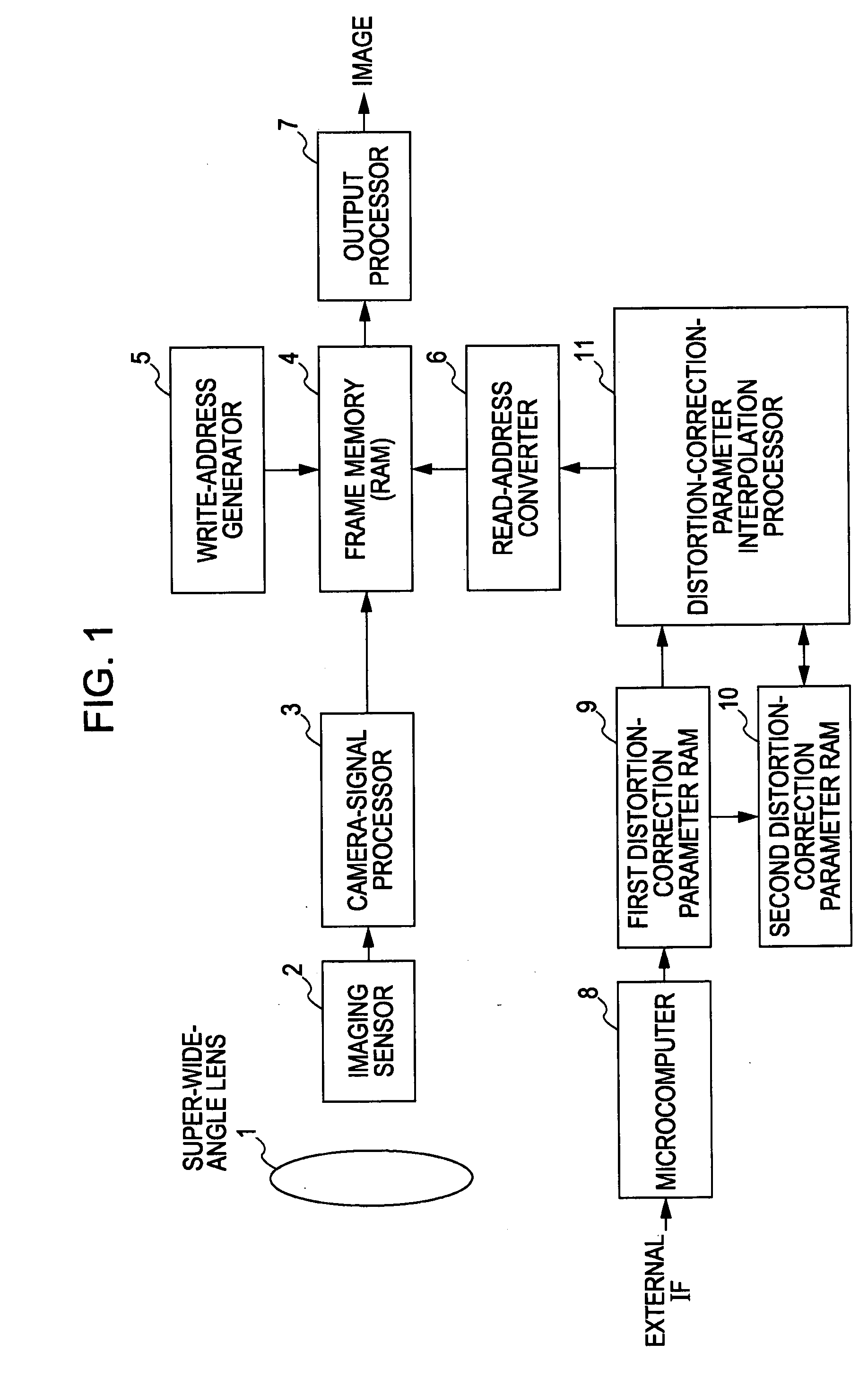
[0035]FIG. 1 is a block diagram illustrating a configuration of a camera device according to an embodiment of the present invention, which captures images in super wide angle and which is used for a monitoring system. The super-wide-angle-imaging camera device includes a super-wide-angle lens 1, an imaging sensor 2, a camera-signal processor 3, a frame memory (RAM) 4, a write-address generator 5, a read-address converter 6, an output processor 7, a microcomputer 8, a first distortion-correction parameter RAM 9, a second distortion-correction parameter RAM 10, and a distortion-correction-parameter interpolation processor 11. Note that the microcomputer 8 is connected to, for example, a host computer (not shown) using an external interface (IF) through a transmission line and the microcomputer 8 is included in a monitoring system. In this case, the camera devi...


PUM


Abstract

In a camera device having a function for converting an image formed by a lens and captured by an imaging element into image data and correcting distortion of the image data caused by distortion aberration of the lens, the camera device includes a first storage unit for storing first distortion correction parameters for correcting the distortion of the image data in a first state, a second storage unit for storing second distortion correction parameters for correcting the distortion of the image data in a second state, and a distortion-correction-parameter interpolator for generating distortion correction parameters through interpolation when transition of the image data from the first state to the second state is performed. The distortion correction parameters indicate states of the image data during the transition of the image data and correct the distortion of the image data caused by the distortion aberration of the lens.

Description

CROSS REFERENCES TO RELATED APPLICATIONS[0001]The present invention contains subject matter related to Japanese Patent Application JP 2006-050396 filed in the Japanese Patent Office on Feb. 27, 2006, the entire contents of which are incorporated herein by reference.BACKGROUND OF THE INVENTION[0002]1. Field of the Invention[0003]The present invention relates to industrial television (ITV) cameras for monitoring systems, and more particularly to distortion correction image processing for images captured by an ITV camera in which the direction of a lens is fixed and the lens is a super-wide-angle lens.[0004]2. Description of the Related Art[0005]A monitoring system for correcting distortion of images captured in super wide angle and compositing the images is generally known. In the general configuration of the monitoring system, an image before distortion correction captured by an ITV camera having a super-wide-angle lens is transmitted to a host computer by an arbitrary transmitter. T...

Claims


Application Information

Patent Timeline
IPC IPC(8): H04N5/76
CPCH04N5/3572H04N5/217H04N23/81H04N25/61
Inventor YODA, KOJI
Owner SONY SEMICON SOLUTIONS CORP
Why Eureka
Eureka Blog
Learn More